


VA Locking Patella Plating System
Eladio Saura-Sanchez, Karl Stoffel, Mark Lee, Cong-Feng Luo, Rodrigo Pesantez, Dean Lorich, David Helfet, Stephen Warner, Christoph Sommer
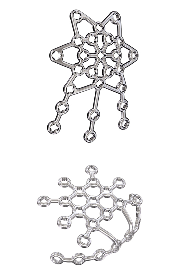 Variable Angle Locking Anterior Patella Plate (upper picture) and Variable Angle Locking Lateral Rim Patella Plate (lower picture).
 Patella fractures account for about 1% of all skeletal fractures. Despite the low incidence, the consequences of inadequate fracture treatment are potentially disabling. Tension band wiring with K-wires or cannulated screws is frequently performed. High rates of symptomatic hardware and loss of fixation have been reported for these fixation techniques.
The Variable Angle Locking Patella Plating System was developed to reduce these complication rates. The system offers two plating solutions in titanium and stainless steel:
- 2.7 mm Variable Angle Locking Anterior Patella Plates
- 2.4/2.7 mm Variable Angle Locking Lateral Rim Patella Plates
The most appropriate plate version can be chosen based on fracture pattern, soft tissue conditions and the preferred surgical technique. Both plate versions have variable angle locking holes which enable up to 15˚ of screw angulation to target small bone fragments and to avoid fracture lines and other hardware. The low-profile plates allow surgeons to achieve stable fixation in simple and complex patella fractures while minimizing soft tissue irritation. The plates can be cut and contoured with dedicated instruments to meet the patient anatomy and to address various fracture patterns. Sutures can be placed through the plate windows to anchor soft tissues. The repeatable surgical technique minimizes the user variation which is observed for tension band wiring.
Clinical problem
Patella fractures account for about 1% of all skeletal fractures [1] with an incidence of approximately 21 per 100,000 per year [2]. Despite the low incidence, the consequences of inadequate treatment are potentially disabling, with possible development of knee stiffness, loss of extension or patellofemoral osteoarthritis. Most patella fractures occur due to direct blunt trauma. The resulting fracture type depends on the trauma mechanism, the energy transmitted to the bone and the bone quality.
Undisplaced or minimally displaced fractures with an intact extensor apparatus can be managed conservatively. In 20–30% of cases surgical treatment is required because the fracture is displaced (displacement of more than 2–3 mm) and/or the extensor mechanism is disrupted. A cohort study [2] with 22,689 patella fractures reported that 26% of the fractures were surgically treated.
Aim of every surgical intervention is to achieve anatomical reduction with joint congruity and to provide high stability for early active range-of-motion exercises [1]. Because of the subcutaneous anterior location, the biomechanical function, and the high level of force transmission (extensor force of up to 3200 N in the quadriceps tendon and up to 2800 N in the ligamentum patellae) [3], stable reconstruction of patellar fractures continues to represent a major surgical challenge [4].
Tension band wiring (TBW) is the most common fixation method. It is performed with two parallel K-wires and a figure-of-8 cerclage wire which is intended to convert tension forces acting on the anterior surface into compression forces at the articular surface. Additional K-wires and cerclage wire or cable configurations can be used to address complex patella fractures. As a low-cost implant solution TBW has proven to be successful if performed with the proper surgical technique. Accurate K-wire placement as well as proper cerclage application and tightening are essential for achieving good clinical results. Limited cerclage-bone contact due to soft tissue interposition and insufficient cerclage tightening, as well as cerclage migration through osteoporotic bone compromise construct stability and may lead to fixation failure. Cannulated screws (as lag or positioning screws), instead of the two K-wires, with TBW (CSTBW) through the screws has been proposed as an alternative fixation technique to increase and maintain primary stability. However, osteoporotic bone often lacks the strength to support a TBW construct and can compromise screw function, which may result in fixation failure before bone union [5].
High rates of symptomatic hardware are reported for TBW and CSTBW. According to a prospective randomized study [6] on transverse patella fractures, the percentage of patients complaining of implant prominence was 5.8% in the CSTBW group and 17.6% in the TBW group. In a retrospective cohort study [7] on comminuted patella fractures 22.9% of patients in the CSTBW group and 40.5% in the TBW group underwent implant removal due to symptomatic hardware. There is a demand for alternative fixation methods to reduce these complication rates.
Patella fracture fixation becomes increasingly challenging with the degree of fracture comminution which can be difficult to assess based on plain x-rays. Lazaro et al [8] investigated the effect of computed tomography (CT) on the classification and treatment plan for patellar fractures. With a CT scan, there was a change in the AO/OTA classification in 66% of cases and a modification of the surgical strategy for 49% of patients. Severely comminuted distal pole fractures were missed on nearly half of the standard images. The study findings underline the importance of a CT scan to realize the complexity of the fracture. Furthermore, it suggests that the occurrence of complex patella fractures is much higher than expected, thus emphasizing the need for better fixation strategies.
Preservation of the patella blood supply must be considered when developing new fixation concepts (implants as well as surgical technique). It has been shown that large blood vessels enter in the lower pole of the patella behind the ligamentum patellae [9]. According to a study [10] about the vascular anatomy of the patella, the medial-sided vessels seem to contribute more significantly to the peripatellar anastomotic ring compared with the lateral-sided vessels [10]. Approach and osteosynthesis should not compromise the dominant blood supply through the inferomedial aspect of the distal pole of the patella. Avoiding inferior pole patellectomy to preserve vascularized bone presents further demands on the fixation concept.
Considering all these aspects, the Patella Task Force (PTF) (medical members: Dankward Höntzsch, David Helfet, Dean Lorich, Sean Nork, Pol Rommens, and Eladio Saura-Sanchez) and the Lower Extremity Expert Group (LEEG) (medical members: Christoph Sommer, Karl Stoffel, Cong-Feng Luo, Rodrigo Pesantez and Mark Lee) of the AO Technical Commission defined as main requirements for the development of a better osteosynthesis solution for the patella:
- Low prominence solution to avoid soft tissue irritations
- High osteosynthesis stability to withstand tensile forces
- Usability for many different fracture patterns (simple and complex fractures) as well as patella morphologies
- Preservation of blood supply at the inferomedial aspect of the distal pole
- Surgical technique with quick learning curve to achieve consistent stability and reproducible results
Solutions
The Variable Angle Locking Patella Plating System addresses these identified requirements with two new plating solutions:
- 2.7 Variable Angle Locking Anterior Patella Plates
- 2.4/2.7 Variable Angle Locking Lateral Rim Patella Plates
Surgeons have the option to choose the most appropriate plating solution based on fracture pattern, soft tissue conditions and individual preferences.
2.7 Variable Angle Locking Anterior Patella Plates
At the onset of the development of this plating solution Eladio Saura-Sanchez reported about his good clinical results using the Locking Calcaneal Plate from DePuy Synthes in an off-label manner for comminuted patella fractures. His fixation concept was to place the calcaneal plate on the anterior surface of the reduced patella and to bend plate arms around the distal patella pole for the insertion of longitudinal locking screws from distal to proximal. In a subsequent step, the patella fracture could be fixed with locking screws from anterior to posterior. Although this fixation concept resulted in stable osteosynthesis, there were usability challenges: the plate required frequent cutting and cumbersome bending to adapt the flat plate to the shape of the patella. Furthermore, the intended bending directions could often not be achieved without cutting selected plate arms compromising construct strength.
To address these issues Eladio Saura-Sanchez envisioned a dedicated, preformed anterior patella plate mimicking the structure of an ice crystal with well distributed locking hole options. In addition to a basic plate, he proposed a patella plate version with some extended plate legs that can be bent around the patella to basket and stabilize fracture fragments as required. Inspired by this vision, the 2.7 Variable Angle Locking Anterior Patella Plates (Fig 1) and instruments were developed by the PTF and LEEG in collaboration with DePuy Synthes under the medical lead of Eladio Saura-Sanchez.
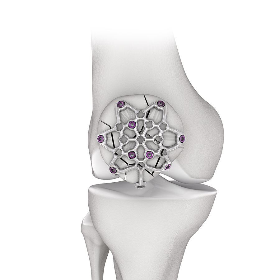 Fig 1 Low profile anterior VA locking plate with various screw fixation options.
 Plate design and plate features
The 2.7 Variable Angle Locking Anterior Patella Plates comprise six plate types (Fig 2) in stainless steel (with 1.8 mm plate thickness) and titanium (with 2.0 mm plate thickness) to address a large variety of fractures in large and small patellae. The plates leverage a smooth, low-profile mesh design to minimize soft tissue irritations, preserve blood supply and facilitate plate adaptation to the bone. While the core plates are intended to be used for simple fractures, the three-hole and six-hole plate versions can be chosen to treat more complex fracture patterns. All plates are precontoured to minimize intraoperative bending and contouring. The arms and legs can be cut to meet the needs for the specific fracture pattern and patient anatomy.
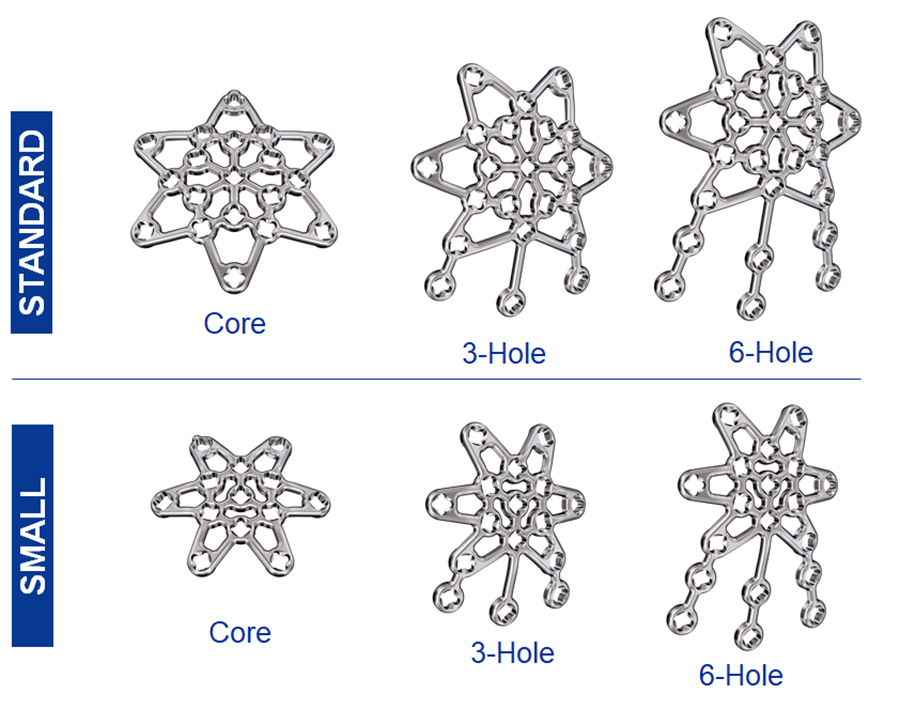 Fig 2 Small and standard size patella plates with 13 to 25 VA locking holes (depending on plate size).
 Plate structure
The plate consists of three plate sections (body, arms, and legs) to allow versatile plate use (Fig 3). Plate arms originate from a rigid plate body to achieve the required anterior bone coverage. The arms can be bent to adapt to the anterior patella surface. Three legs extend from the arms/body of the three-hole and six-hole plate versions. They can be oriented and bent around the patella to secure fracture fragments.
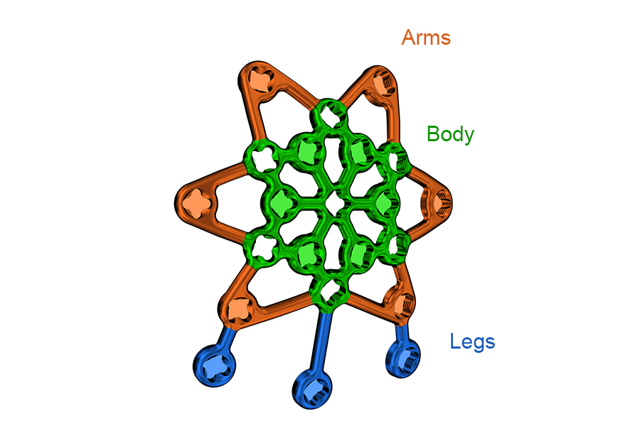 Fig 3 Plate sections of a three-hole patella plate.
 Plate design and plate features
There are several plate features to ease and improve patella fracture fixation (Fig 4): variable angle (VA) locking holes enable up to 15° of screw angulation to target small bone fragments and to avoid fracture lines as well as other hardware. The screw holes accept 2.4 mm and 2.7 mm VA locking and cortex screws (2.4 mm screws are only for use in small, non-load bearing fragments). There is a tab on one of the plate arms for orientation purposes when the plate is contoured ex-situ. The tab is not required in the three-hole and six-hole plate versions since the plate legs help with proper plate orientation. The plate windows in the open architecture plate can be used to attach soft tissues with sutures.
The performance of the plate was explored in a biomechanical test at the AO Research Institute Davos. The anterior patella plate provided significantly higher stability in simple and complex fractures compared with modified TBW.
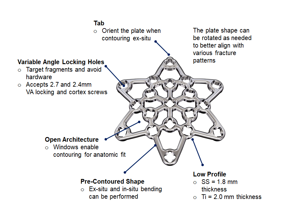 Fig 4 Plate features of the core plate which is available in stainless steel (SS) and titanium (Ti).
 Plate templates
There are two sterile plate templates available (small and standard six-hole plate sizes) to help determine proper sizing and contouring of the implant (Fig 5). The preformed templates are provided in the six-hole configuration only, which can be used to approximate sizing and contouring for core, three-hole and six-hole implants. They are malleable and include holes for K-wire fixation.
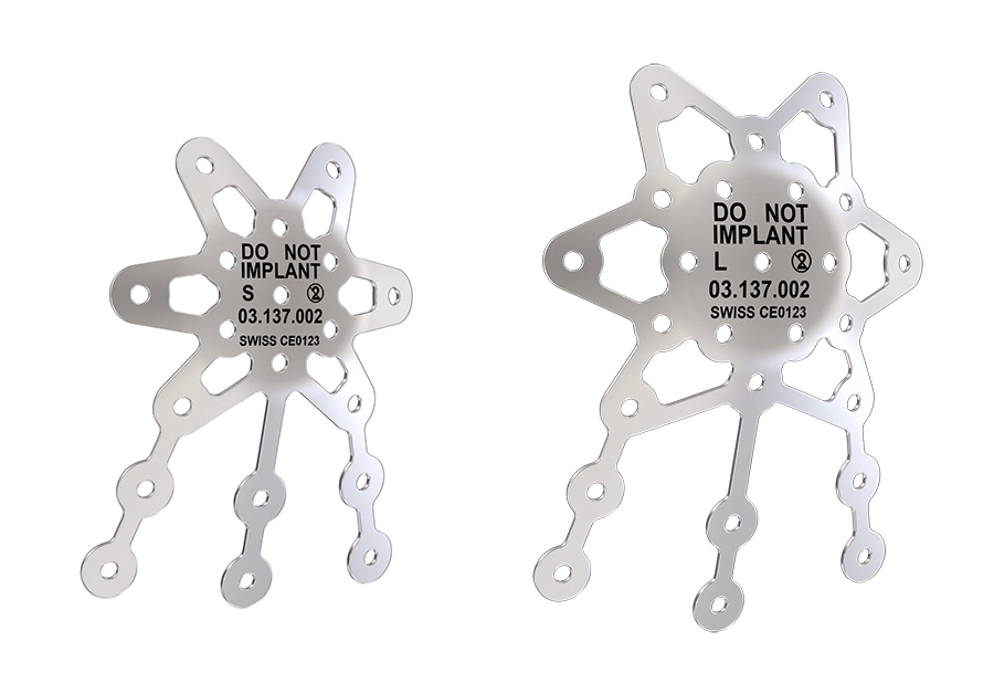 Fig 5 Small (left) and standard (right) plate templates.
 Surgical technique
The surgical technique which was refined throughout several anatomy labs (Fig 6) comprises the following steps:
1. Position the patient supine with the knee in slight flexion.
2. Create a midline or parapatellar incision (a lateral parapatellar incision is recommended to preserve the inferomedial blood supply).
3. Reduce the fracture fragments (with reduction forceps and K-wires). It can be beneficial to evert the patella to achieve accurate fracture reduction and joint congruency under direct vision (Fig 7).
4. Use the templates to determine the appropriate plate size, configuration, and orientation.
5. Cut the plate legs and file cutting edges (as needed).
6. Contour the plate with the plate bending instruments (as needed). Avoid bending the plate beyond what is required to match the anatomy. Repeated reverse bending may weaken the plate and lead to premature plate failure, especially in titanium plates.
7. Position the plate according to the fracture pattern and patient anatomy with provisional plate fixation using the 1.6 mm threaded compression wires.
8. Insert screws (VA locking screws and cortex screws).
a) Place the distal to proximal screw(s) first when using the three-hole or six-hole plates.
b) Drill measure, and place the anterior to posterior monocortical locking screws.
c) Final tightening of the VA locking screws with 1.2 Nm torque limiter.
9. Use sutures through the plate windows to anchor soft tissues (as needed). Sutures must not be placed through the locking holes.
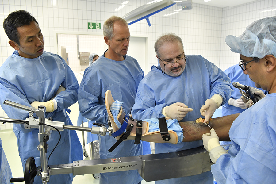 Fig 6 Anatomy lab to determine the optimal surgical technique. From left to right: Mark Lee, Christoph Sommer, Eladio Saura-Sanchez, and Rodrigo Pesantez.
 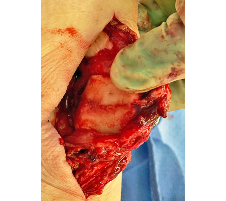 Fig 7 Lateral parapatellar arthrotomy and patella eversion for direct visual reduction of the articular surface (courtesy of Mark Lee).
 In most complex fractures a three-hole or six-hole plate is useful for bending the plate legs around the rim of the patella to basket and fix bone fragments. The plate can be oriented on the patella as needed to utilize the plate legs for fracture fixation. For distal to proximal screw placement through the distal patella pole (with a pole screw) a longitudinal split in the patellar tendon is required to insert the plate leg. Sometimes proximal to distal screw placement through the quadriceps tendon might be preferred. The VA locking or cortex screws can be used as pole screws (Fig 8). It is important to place the pole screw(s) before the insertion of the anterior to posterior locking screws.
A minimum of two screws per fragment are recommended. If this is not possible, augmentation techniques (eg, sutures) can be applied. The 2.4 mm anterior-posterior locking screws may only be used in small, non-load bearing fragments.
For the complete surgical technique, refer to the DePuy Synthes Surgical Technique Guide.
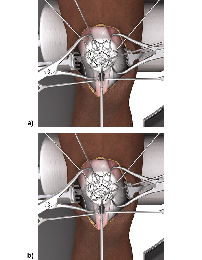 Fig 8 Placing a VA locking screw as pole screw (a) prevents screw head prominence and provides angular stable fixation. A cortex screw can be used as pole screw (b) to bring the plate down to the bone and to achieve interfragmentary compression with a lag screw technique.
 2.4/2.7 Variable Angle Locking Lateral Rim Patella Plates
The development of the 2.4/2.7 Variable Angle Locking Lateral Rim Patella Plates was based on the fixation concept published by Dean Lorich, Stephen Warner, and David Helfet in 2015 [11]. The authors used the Variable Angle LCP Mesh Plate 2.4/2.7 (part of the Variable Angle LCP Forefoot/Midfoot System 2.4/2.7) for multiplanar fixation of patella fractures. The surgical technique included a lateral parapatellar arthrotomy to avoid the predominant vascularity to the patella coming in inferomedially and to allow for eversion of the patella to directly visualize the articular surface during reduction and plate fixation. The mesh plate had to be cut to size and contoured to fit around the lateral rim of the reduced patella and the anterior cortical surface.
Plate design and plate features
The 2.4/2.7 Variable Angle Locking Lateral Rim Patella Plates are offered in both a small and a standard size (Fig 9) with various screw hole options for each size to provide fixation for various patella fracture patterns. These plates are an evolution of the mesh plate to ease plate application and to optimize plate function in patella fracture treatment. The plates are offered in stainless steel (with 1.8 mm plate thickness) and titanium (with 2.0 mm plate thickness) and contain the same smooth, low-profile mesh design (Fig 10) and VA locking hole technology as the 2.7 Variable Angle Locking Anterior Patella Plates. The same screws and instruments are used for plate application as for the 2.7 Variable Angle Locking Anterior Patella Plates. The plates are precontoured and can be cut as needed with the plate cutter in the instrument tray.
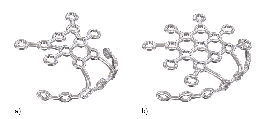 Fig 9 The 2.4/2.7 Variable Angle Locking Lateral Rim Patella Plates are available in a small plate version with 18 VA locking holes (a) and a standard plate version with 24 VA locking holes (b) in stainless steel and titanium.
 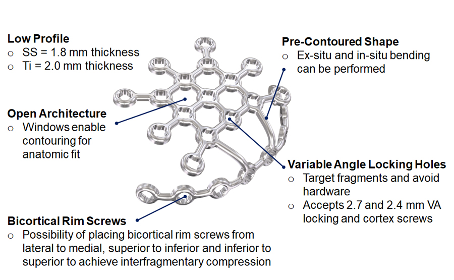 Fig 10 Plate features of the 2.4/2.7 Variable Angle Locking Lateral Rim Patella Plate.
 Plate structure
The 2.4/2.7 Variable Angle Locking Lateral Rim Patella Plate consists of two plate sections: anterior body and lateral rim (Fig 11).
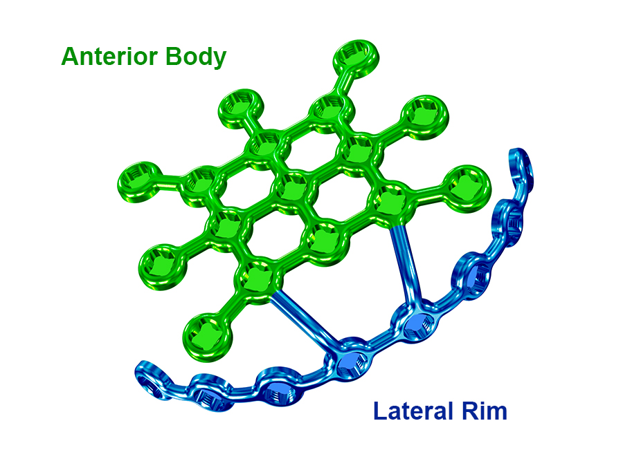 Fig 11 Anterior body and lateral rim of the standard 2.4/2.7 Variable Angle Locking Lateral Rim Patella Plate.
 Plate templates
There are two sterile plate templates (Fig 12) available (small and standard) to help determine proper sizing and contouring of the implant. They are malleable and include holes for K-wire fixation.
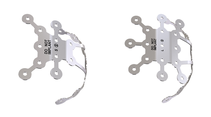 Fig 12 Small (left) and standard (right) preformed templates are provided which can be used to approximate sizing and contouring.
 Surgical technique
The 2.4/2.7 Variable Angle Locking Lateral Rim Patella Plate utilizes the same surgical steps as the 2.7 Variable Angle Locking Anterior Patella Plates; however, the plate is placed along the lateral rim of the patella instead of the anterior surface. To apply the plate on the rim a lateral peripatellar retinacular release is necessary. This assures a perfect rim fit for the plate but also facilitates patella eversion for an anatomical reduction of the articular surface. Often the retinaculum needs to be repaired to the plate.
The lateral rim of the plate is contoured to sit beneath the patellar ligament and the quadriceps tendon (Fig 13). The plate is placed so that it does not interfere with the articular surface. Subsequently, the bridges connecting the lateral rim to the anterior body can be bent such that the latter sits against the anterior surface of the patella. Additional contouring of the anterior body is performed from the center outward. Avoid bending the plate beyond what is required to match the anatomy. Repeated reverse bending may weaken the plate and lead to premature plate failure, especially in titanium plates.
First place bicortical cortex screws in the rim portion of the plate (Fig 14). Once these are secured, insert the unicortical anterior to posterior variable angle locking screws. A minimum of four bicortical rim screws per construct is recommended; however, if this is not possible consider an additional augmentation technique.
For the complete surgical technique, refer to the DePuy Synthes Surgical Technique Guide.
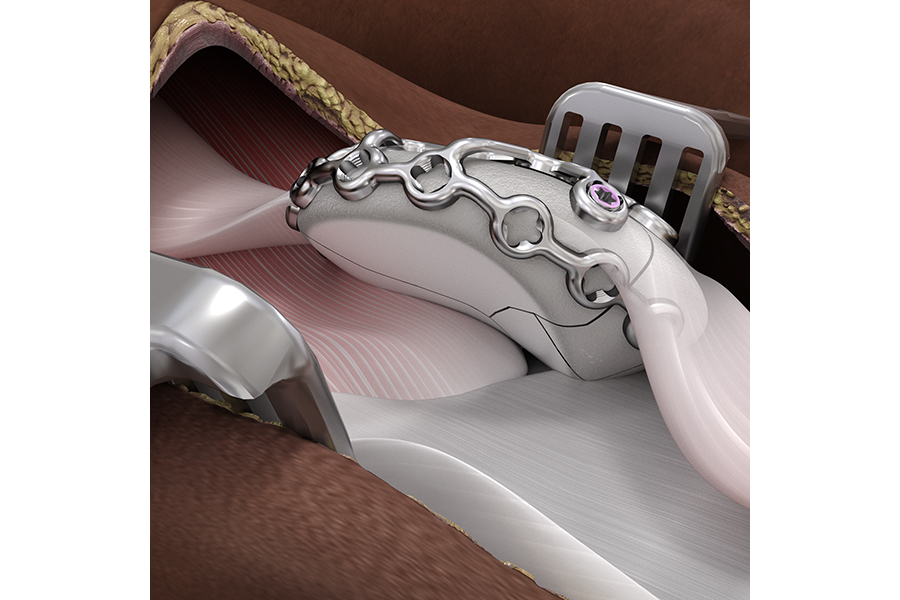 Fig 13 Everted patella indicating the placement of the lateral plate rim beneath the patellar ligament and the quadriceps tendon.
 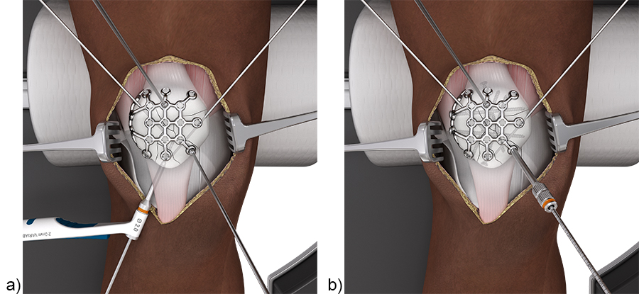 Fig 14 Placing the bicortical cortex rim screws first (a) optimizes screw purchase, ensures the plate is compressed to the bone and minimizes the likelihood of screw interference when placing the anterior to posterior locking screws (b).
 Intended use and indications
Both plating solutions have the same intended use and indications:
- Intended use: The DePuy Synthes VA Locking Patella Plating System is intended to provide internal bone fixation for simple, complex, and comminuted patellar fractures.
- Indications: The DePuy Synthes VA Locking Patella Plating System is indicated for the fixation and stabilization of patellar fractures in normal and osteopenic bone in skeletally mature patients.
References
1. Neumann MV, Niemeyer P, Südkamp NP, et al. Patellar fractures: a review of classification, genesis and evaluation of treatment. Acta Chir Orthop Traumatol Cech. 2014;81(5):303–312.
2. Vestergaard V, Pedersen AB, Tengberg PT, et al. 20-year trends of distal femoral, patellar, and proximal tibial fractures: a Danish nationwide cohort study of 60,823 patients. Acta Orthop. 2020 Feb;91(1):109–114.
3. Huberti HH, Hayes WC, Stone JL, et al. Force ratios in the quadriceps tendon and ligamentum patellae. J Orthop Res. 1984;2(1):49–54.
4. Gwinner C, Märdian S, Schwabe P, et al. Current concepts review: Fractures of the patella. GMS Interdisc Plast Reconstr Surg DGPW. 2016 Jan 18;5: Doc01.doi: 10.3205/iprs000080.
5. Matthews B, Hazratwala K, Barroso-Rosa S. Comminuted patella fracture in elderly patients: systematic review and case report. Geriatr Orthop Surg Rehab. 2017 Sep;8(3):135–144.
6. Nagakiran KV, Wooly S, Soraganvi P, et al. Screws vs solid wires: the better method for transverse patellar fracture fixation—a prospective randomised study. J Evidence Based Med Healthcare. 2021;8(17):1163–1168.
7. Zhu XZ, Huang TL, Zhu HY, et al. A retrospective cohort study on prevalence of postoperative complications in comminuted patellar fractures: comparisons among stabilized with Cannulated-Screw, Kirschner-Wire, or Ring-Pin Tension Bands. BMC Musculoskelet Disord. 2021 Jan 11;22(1):60.
8. Lazaro LE, Wellman DS, Pardee NC, et al. Effect of computerized tomography on classification and treatment plan for patellar fractures. J Orthop Trauma. 2013 Jun;27(6):336–344.
9. Scapinelli R. Blood supply of the human patella. Its relation to ischaemic necrosis after fracture. J Bone Joint Surg Br. 1967 Aug;49(3):563–570.
10. Lazaro LE, Cross MB, Lorich DG. Vascular anatomy of the patella: implications for total knee arthroplasty surgical approaches. Knee. 2014 Jun;21(3):655–660.
11. Lorich DG, Warner SJ, Schottel PC, et al. Multiplanar fixation for patella fractures using a low-profile mesh plate. J Orthop Trauma. 2015 Dec;29(12):e504–510.
Instrument tray
- Two large reduction forceps for reducing fragments of small and large patellae in simple and complex cases.
- Four 1.6 mm compression wires with 10 mm thread and sphere for compressing the plate to the bone for provisional fixation. The sphere is self-seating in the recess of the VA hole.
- One straight and one curved plate bending instrument for appropriate in-situ and ex-situ bending of the plate (Fig 2).
- Plate cutter with small cutting jaws for plate cutting close to the VA holes.
- Plate file for smoothing the plate edges after cutting.
- Depth gauge for 2.7 mm screws for directly reading the required screw length.
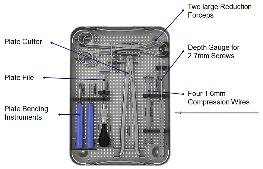 Fig 1 Instrument tray for VA Locking Anterior Patella Plate and VA Locking Lateral Rim Patella Plate.
 Bending instruments
The straight and curved plate bending instruments (Fig 2a) should be inserted in adjacent plate holes to bend the plate between the VA locking holes. The instruments have a tip with a special cloverleaf design which maintains the integrity of the VA locking holes during bending. The cloverleaf shape allows the bender orientation to be rotated in 90° increments to obtain appropriate leverage for bending (Fig 2b).
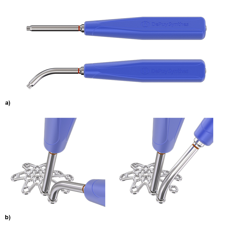 Fig 2a-b Straight and curved plate bending instruments (a). The instruments can be rotated in 90° increments to obtain an appropriate leverage for bending (b).
 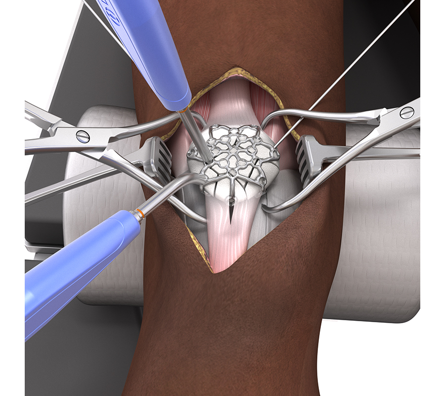 Fig 3 In-situ bending of the VA Locking Anterior Patella Plate.
 Clinical cases
Case 1
Treatment of a fragmented distal pole patella fracture with a three-hole patella plate (by Christoph Sommer, Kantonsspital Chur, Switzerland).
A 73-year-old woman sustained a right 34-C3.1 patella fracture during a hiking injury (Fig 1). X-ray analysis revealed that the distal pole was fractured in four fragments (Fig 2). After fracture reduction, a three-hole plate was used with three inferior to superior locking screws in the coronal plane through the holes of the plate legs and five anterior to posterior locking screws (Fig 3 and Fig 4).
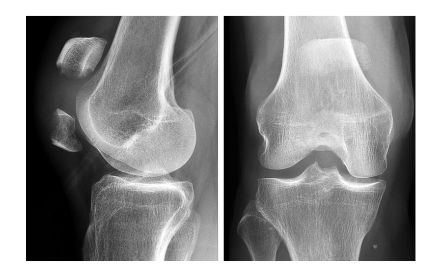 Fig 1 Preoperative ML and AP x-rays.
 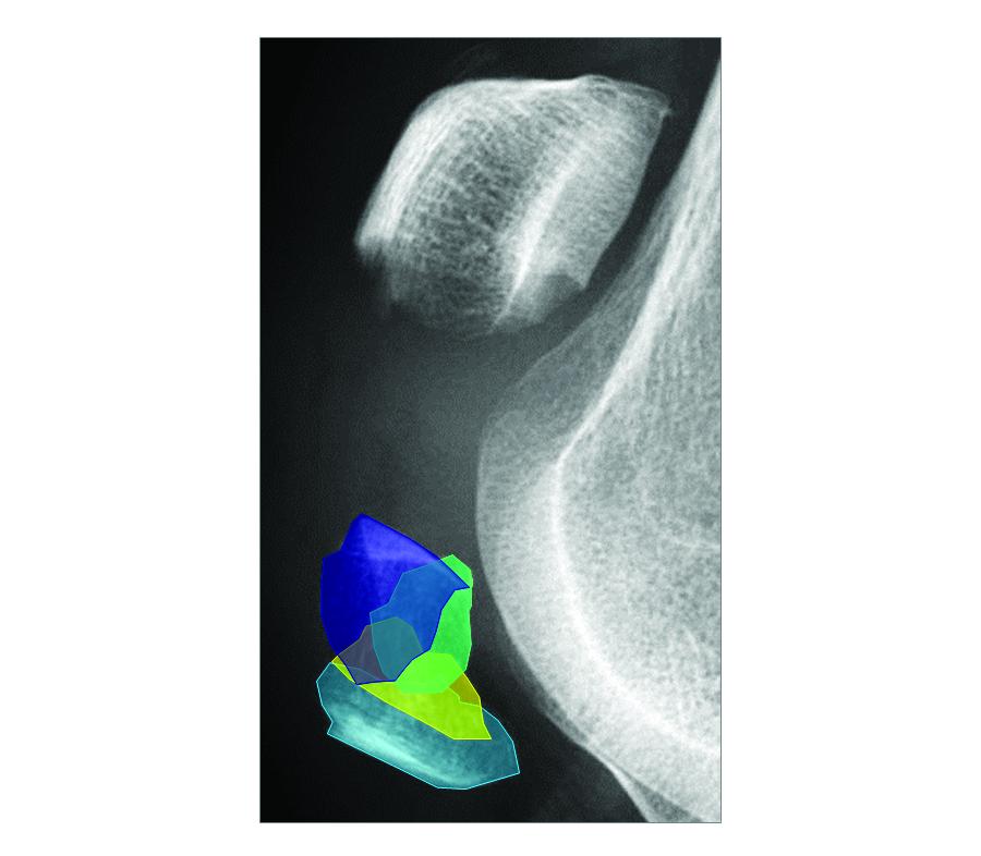 Fig 2 Enlarged preoperative ML x-ray with four distal pole fragments including a coronal fracture line.
 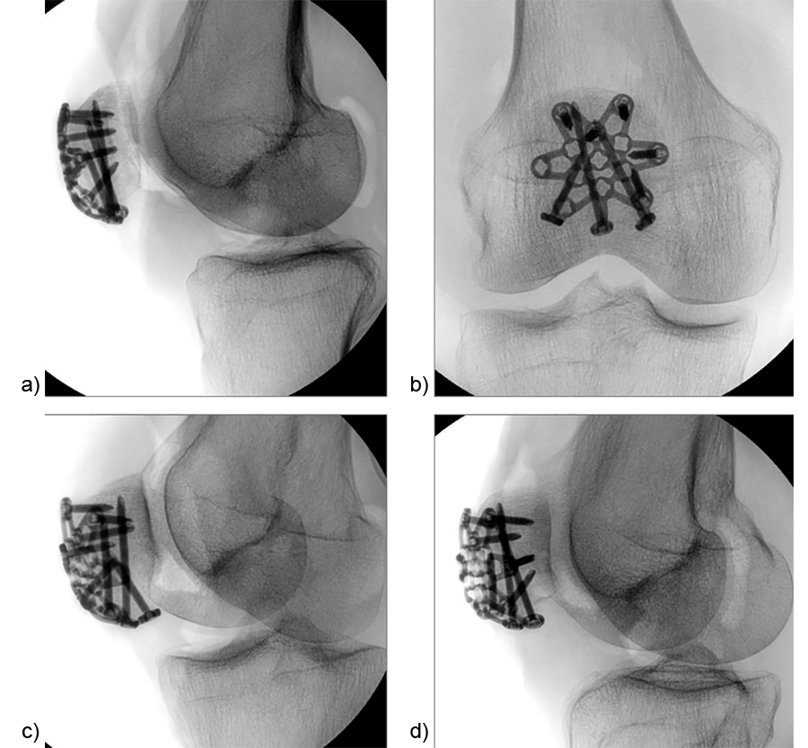 Fig 3 Intraoperative x-rays. True ML (a), true AP (b), obliquelateral facet (c), and oblique medial facet (d).
 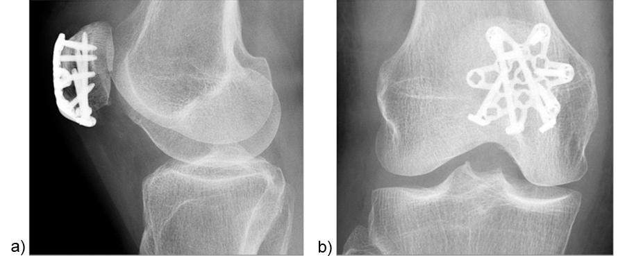 Fig 4 ML (a) and AP (b) x-rays two days postoperatively.
 Case 2
Treatment of a complex patella fracture with a three-hole patella plate (by Eladio Saura-Sanchez, University Hospital of Elche, Spain).
A 71-year-old obese woman with osteoporosis sustained a fall from standing height with a direct blunt trauma on the left knee. It was impossible for her to walk or extend the knee. X-rays revealed a complex patella fracture with a comminuted distal pole (Fig 5).
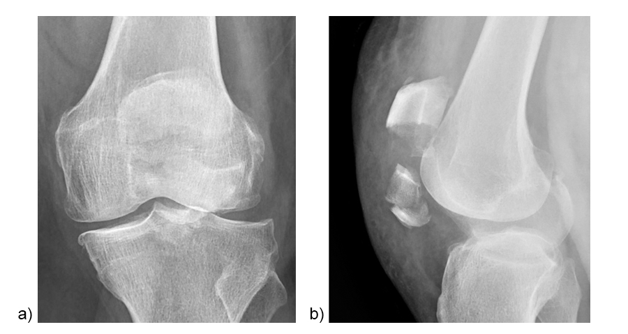 Fig 5 Preoperative ML (a) and AP (b) x-rays: complex patella fracture with inferior pole avulsion and severe displacement.
 A CT scan was performed to assess the complexity of the fracture pattern (Fig 6).
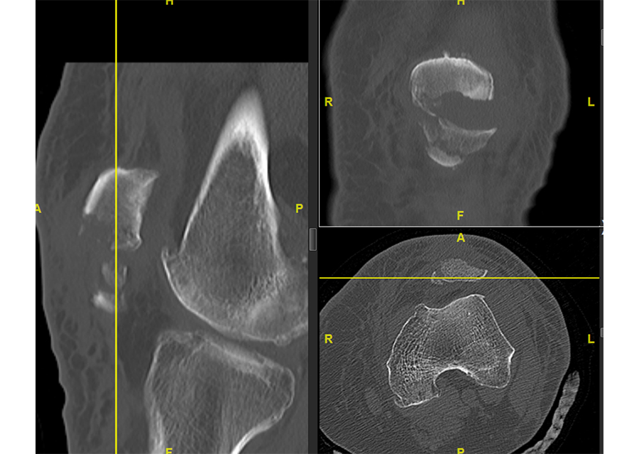 Fig 6 The CT scan revealed the complexity of the fracture.
 A direct anterior approach was chosen (Fig 7a). The extensor mechanism was completely ruptured (Fig 7b).
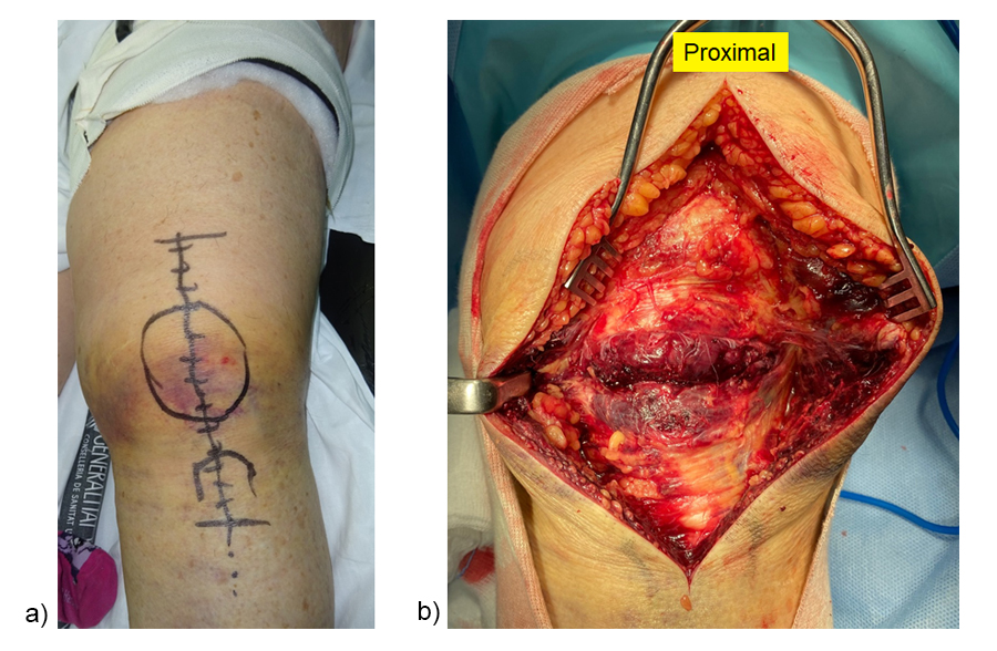 Fig 7 Surgical approach (a) and initial exposure of the fracture with complete, transverse disruption of the extensor mechanism (b).
 After intrafocal identification of the fracture fragments, bone anchors with augmentation sutures were placed in the proximal pole (Fig 8a). The sutures passed intraosseous toward the patellar tendon. A lateral parapatellar incision was performed for eversion of the patella to achieve articular reduction of the main fragments under direct vision (Fig 8b). K-wires were used for temporary fixation of the fracture fragments. A headless screw was inserted as lag screw to compress the two main articular fragments.
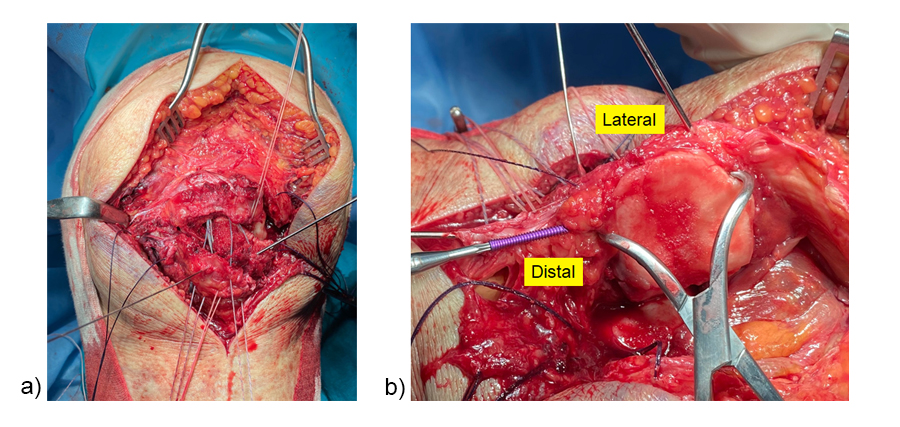 Fig 8 Intraosseous suture placement (a) and eversion of the patella for fracture reduction (b).
 After fracture reduction and temporary fixation, the plate template was used on the patella to select the appropriate plate size and to determine the best plate position with the desired location for the inferior to superior locking pole screw through the central plate leg (Fig 9).
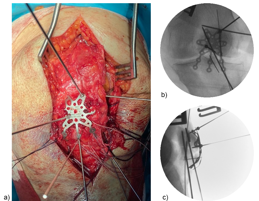 Fig 9 The plate template was pinned to the patella with the help of threaded compression wires (a). AP (b) and ML x-ray (c) of the template position.
 A standard three-hole patella plate was chosen and bent according to the template. A central trans-patellar tendon stab incision was made to insert the middle plate leg when positioning the plate (Fig 10). The plate was provisionally fixed to the proximal patella fragment. The inferior to superior pole screw was inserted first as the 'primary' screw through the preselected plate hole of the middle plate leg to prevent collision with subsequent 'secondary' anteroposterior screws. Bicortical pole screw placement increases the stability of the construct. In this plate configuration the plate was used as a “basket plate” to stabilize the fracture. A second pole screw was inserted through the lateral plate leg.
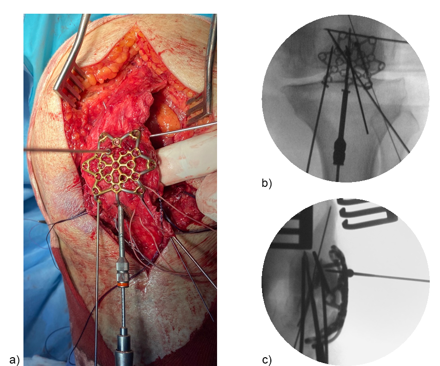 Fig 10 Plate application and drilling of the hole for the pole screw through the drill sleeve placed in the central plate leg (a). AP (b) and ML x-ray (c) during drilling.
 The plate fixation was finalized by placing the monocortical AP locking screws. Subsequently, the sutures were tightened to the patellar tendon and the extensor mechanism (Fig 11). The plate may help to enhance the suture fixation.
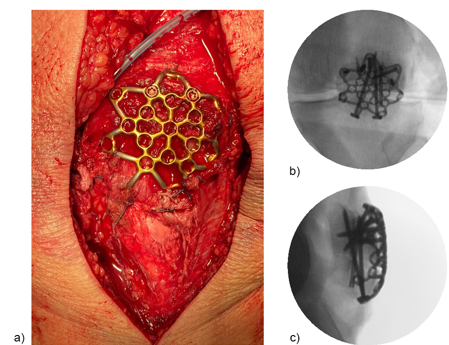 Fig 11 Final plate fixation and suture augmentation (a). Intraoperative AP (b) and ML x-ray (c) of the fixation construct.
 Figure 12 illustrates the final fixation construct. The patient was allowed to perform early active knee movement at 2 weeks.
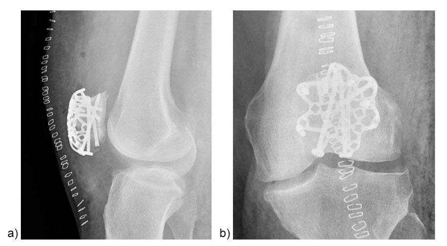 Fig 12 Postoperative ML (a) and AP (b) x-rays.
 Patella fracture treatment - Variable Angle Locking Patella Plating System
Hazards and labeling
Due to varying countries’ legal and regulatory approval requirements, consult the appropriate local product labeling for approved intended use of the products described on this website. All devices on this website are approved by the AO Technical Commission. For logistical reasons, these devices may not be available in all countries worldwide at the date of publication.
Legal restrictions
This work was produced by AO Foundation, Switzerland. All rights reserved by AO Foundation. This publication, including all parts thereof, is legally protected by copyright.
Any use, exploitation or commercialization outside the narrow limits set forth by copyright legislation and the restrictions on use laid out below, without the publisher‘s consent, is illegal and liable to prosecution. This applies in particular to photostat reproduction, copying, scanning or duplication of any kind, translation, preparation of microfilms, electronic data processing, and storage such as making this publication available on Intranet or Internet.
Some of the products, names, instruments, treatments, logos, designs, etc referred to in this publication are also protected by patents, trademarks or by other intellectual property protection laws (eg, “AO” and the AO logo are subject to trademark applications/registrations) even though specific reference to this fact is not always made in the text. Therefore, the appearance of a name, instrument, etc without designation as proprietary is not to be construed as a representation by the publisher that it is in the public domain.
Restrictions on use: The rightful owner of an authorized copy of this work may use it for educational and research purposes only. Single images or illustrations may be copied for research or educational purposes only. The images or illustrations may not be altered in any way and need to carry the following statement of origin “Copyright by AO Foundation, Switzerland”.
Check www.aofoundation.org/disclaimer for more information.
If you have any comments or questions on the articles or the new devices, please do not hesitate to contact us.
“approved by AO Technical Commission” and “approved by AO”
The brands and labels “approved by AO Technical Commission” and “approved by AO”, particularly "AO" and the AO logo, are AO Foundation's intellectual property and subject to trademark applications and registrations, respectively. The use of these brands and labels is regulated by licensing agreements between AO Foundation and the producers of innovation products obliged to use such labels to declare the products as AO Technical Commission or AO Foundation approved solutions. Any unauthorized or inadequate use of these trademarks may be subject to legal action.
AO ITC Innovations Magazine
Find all issues of the AO ITC Innovations Magazine for download here.
Innovation Awards
Recognizing outstanding achievements in development and fostering excellence in surgical innovation.