


Universal Small Fragment System
Christoph Sommer, Mark Lee, Christina Kabbash, Fabio Suarez, Chunyan Jiang
Clinical problems and challenges
Over time, the collaboration of the AOTK System and DePuy Synthes has resulted in the development of numerous implants and instruments to address specific clinical problems. Surgeons can choose from a large variety of standard and anatomically pre-contoured plates with instruments for application of conventional screws, locking screws and variable angle locking screws. The sequential introduction of plating and screw technologies has led to a total number of more than 20 DePuy Synthes sets to support small fragment procedures involving shoulder, clavicle, elbow, tibia and fibula anatomies. Surgical treatment of small bone trauma occurs worldwide about every 18 seconds and represents about 25% of all bone trauma cases [1, 2, 3]. The number of sets and the material volume for these frequently performed procedures place a significant burden on hospital resources in terms of reprocessing, storing and transporting the equipment [4, 5]. It is also difficult for surgical teams to remain proficient in using so many different systems. Training staff to use such a large portfolio of osteosynthesis material is also a considerable cost factor for the healthcare provider. In addition to this, the large number of parts in the sets entails an increased opportunity for missing and / or broken instruments. Realizing this burden on all involved stakeholders resulted in the clear need to provide a simplified solution for small bone procedures which improves ease of use as well as hospital efficiency.
Approach to define a solution
Since one of the goals of this improvement initiative was to ensure universal instrument use across small bone anatomy, the AOTK System formed a dedicated Task Force by involving medical members of several different AOTK Expert Groups: Upper Extremity, Lower Extremity, Hand and Foot. The Task Force members were from different continents of the world which allowed to also consider potential regional aspects and demands. Coming up with a new set configuration for small bone procedures was an ideal opportunity to review and optimize individual instruments in terms of surgical steps required and streamlined workflow. Efforts were made to improve instrument ergonomics as well as cleaning and sterilization processes.
New solution
From a conceptional viewpoint, the new Universal Small Fragment (USF) System was designed to perform more procedures with less equipment. This is markedly influenced by how the system is provided to the surgeon depending on the intended procedure. The USF System consists of two components: 1) Core Set and 2) Modular Anatomic Implant Trays. The Core Set (Fig 1) is composed of a USF Insertion Tray (instruments for 2.7 mm and 3.5 mm non-locking, locking and variable angle locking implants), a USF Standard Plate Tray (2.7 mm and 3.5 mm locking implants for multi-anatomy use), an Auxiliary Tray, a USF Reduction Tray (features common reduction instruments) and a USF Screw Rack which can be customized. There is also a reduced Core Set option which comprises an Insertion Tray without drill bits, an Auxiliary Tray and a Reduction Tray.
 Fig 1 USF System Core Set: Insertion Tray, Standard Plate Tray (Stainless Steel and Titanium options), Auxiliary Tray (for customization), Reduction Tray, Screw Rack (Stainless Steel and Titanium options).
 Eight streamlined anatomic implant trays (Elbow Implant Set, Shoulder / Clavicle Implant Set, VA LCP Proximal Tibia Implant Set, LCP Proximal Tibia Implant Set, VA LCP Distal Tibia Implant Set, LCP Distal Tibia Implant Set, VA LCP Distal Fibula Implant Set, LCP Distal Fibula Implant Set) which include the majority of implants (to cover about 80% of the procedures; remaining implant portfolio is provided sterile packed), can be coupled with the core set to support specific small bone procedures (Fig 2).
All upper extremity trays as well as the LCP lower extremity trays are available in Stainless Steel and Titanium options. The VA LCP lower extremity trays are only provided in Stainless Steel. The modular concept of the USF System offers the flexibility to build different system configurations to meet the surgeon's needs. This approach also helps to reduce the weight of the required sets to be transferred to the operating room.
The USF System Core Set can support all 2.7 mm / 3.5 mm non-locking, locking and variable angle locking plate technologies.
 Fig 2 USF System Core Set and eight streamlined anatomic implant trays.
 Templates for Universal Small Fragment System
Templates for plating have gained importance because of the increasing request of sterile packaging of plates in many regions of the world. To enable proper implant selection, we are pleased to report that new templates complement all anatomic plate types of the USF System.
To provide an economical and effective solution, the new templates are manufactured using 3D printing technology and utilizing non-implantable stainless steel. The templates mimic the shape of the respective anatomic plates (Fig 3) and allow reprocessing for repeated use. They are radiopaque, and K-wire holes indicate the location of plate holes (Fig 4). To minimize system complexity, templates are provided for the shortest and most common length of an implant. Determination of other plate sizes can be deduced from straight measurements. The templates are labeled DO NOT BEND as they will no longer mimic the partnered implant, and repeated bending can result in template breakage.
The following plate families are supported by the templates:
Upper extremity
- Proximal humerus: LCP Proximal Humerus (PHILOS) and LCP Periarticular Proximal Humerus
- Clavicle: LCP Superior Anterior and Superior Clavicle (with extension and standard), VA LCP Anterior Clavicle
- Elbow: VA LCP Medial Distal Humerus, VA LCP Lateral Distal Humerus, VA LCP Posterolateral Distal Humerus, VA LCP Proximal Olecranon, VA LCP Olecranon, LCP Extra-articular Distal Humerus, LCP Hook
Lower extremity
- Proximal Tibia: VA LCP Proximal Tibia (small and large bend), LCP Proximal Tibia (standard and low bend), LCP Posteromedial Proximal Tibia, LCP Medial Proximal Tibia
- Distal Tibia: VA LCP Medial Distal Tibia, VA LCP Anterolateral Distal Tibia, LCP Anterolateral Distal Tibia, VA LCP Posterolateral Distal Tibia, VA LCP Posterolateral Distal Tibia T-Plate, LCP Low Bend Medial Distal Tibia
- Distal Fibula: VA LCP Lateral Distal Fibula, LCP Lateral Distal Fibula, LCP Hook
 Fig 3 Anatomic template for the 11-hole LCP Anterolateral Distal Tibia plate.
  Fig 4 Radiopaque appearance of the template for the VA LCP Medial Distal Tibia plate on a human anatomical specimen.
 Benefits of the new USF System
The innovative concept of the USF System allows existing and future 2.7 mm / 3.5 mm implants to be supported with only one core set of instruments, which markedly reduces operating room complexity and improves workflow efficiency. Compared to the existing system with more than 20 sets, the USF System with its 8 modular anatomic implant trays has the following three signature benefits:
- Improved instrument and system ease of use by operating room teams and hospital staff
- Improved efficiency through reduction in instruments and trays needed for small fragment procedures
- Reduction in hospital costs associated with maintaining equipment.
The USF System is the first trauma platform to receive an Earthwards recognition for providing a more environmentally sustainable solution. The streamlined design, in-tray washing and eliminating the need to use additional sets per procedure are features which help to markedly reduce water and energy consumption (estimated reduction of up to 56%).
Introduction into AO teaching
It is intended that the USF System for small bone procedures gradually replaces the more than 20 existing implant and instrument sets. This entails that all teaching materials have to be updated which is coordinated with AOTrauma Education. The introduction into AO courses is planned for end of 2020 after the USF System has received AOTK 'Standard' approval (current AOTK approval category is 'Recommended').
References
1) Millennium Research Group DRG: Medtech 360, Trauma Devices | Market Analysis | US | 2018.
2) Millennium Research Group DRG: Medtech 360, Trauma Devices and Large-Joint Reconstructive Implants | Market Analysis | Asia Pacific | 2016.
3) Millennium Research Group DRG: Medtech 360, Trauma Devices | Market Analysis | Europe | 2017.
4) Delatore P, Bourque M, Taylor J, Ferko N. The value of SKU reduction and standardization initiatives within a hospital system. Value in Health. 2016; Volume 19, Issue 3, Page A293.
5) Richardson DM, Rupp VA, Long KR, Urquhart MC, et al. Using lean methodology to decrease wasted RN time in seeking supplies in emergency departments. J Nurs Adm. 2014; Nov;44(11):606-11.
The USF System Core Set comprises, in addition to existing and well-established instruments, several new and optimized instruments for intuitive use.
Guides for drilling
All guides for drilling have engraved figures which are clearly visible to indicate the drill bit diameters which are supposed to be used.
All instruments for preparing screw holes have color-coded labeling and marks to indicate their proper use depending on the screw size:
- Orange: For 2.7 mm screws
- Black: For 3.5 mm screws
The new 2.7 mm and 3.5 mm Non-Locking Drill Guides (Fig 3) have a single-banded mark on the instrument side for drilling a lag screw hole, and a double-banded mark on the instrument side for preparing a gliding hole. There are threaded 2.7 mm and 3.5 mm Neutral Sleeve Adapters which can be mounted to the lag screw side (single-banded side) of the Non-Locking Drill Guides to neutralize cortex screws. The lag screw side of the 3.5 mm Non-Locking Drill Guide and the 3.5 mm Neutral Sleeve Adapter are coated in gold-color to indicate that they are used together and in combination with the 2.5 mm drill bit which is also coated in this color.
 Fig 3a 2.7 mm and 3.5 mm Non-Locking Drill Guides.
  Fig 3b Design features as exemplified on the 3.5 mm Non-Locking Drill Guide. Instead of using the spring-loaded feature of the former drill guide to drill a hole for a neutralized cortex screw, a Neutral Sleeve Adapter can be mounted to the lag screw side of the instrument to achieve the neutral position.
 The new 2.7 mm and 3.5 mm Variable Angle Drill Guides (Fig 4) have on one instrument side a tubular, freehand guide with a variable angle spherical tip which is marked by a single band and on the other side a 30-degree cone to drill within the appropriate range of applying variable angle locking screws.
 Fig 4a 2.7 mm and 3.5 mm Variable Angle Drill Guides.
  Fig 4b Design features as exemplified on the 3.5 mm Variable Angle Drill Guides.
 2.0 mm and 2.8 mm Threaded Guides (Fig 5) with single-banded marks are provided for drilling of 2.7 mm and 3.5 mm locking screw holes and variable angle locking screw holes at a nominal angle. These guides have an internal recess to allow their application to the plate with a StarDrive screwdriver. The Insertion Tray contains four 2.8 mm Threaded Guides and two 2.0 mm Threaded Guides.
 Fig 5a Threaded Guides for drilling holes for 2.7 mm and 3.5 mm locking screws and variable angle locking screws at a nominal angle.
  Fig 5b Design features are described and exemplified for the 2.8 mm Threaded Guide.
 Drill Bits
All quick coupling drill bits have color-coded labeling and coating for easy identification and coordinated use with the drill guides.
Drill bits with orange marks for drilling of 2.7 mm screw holes:
- 2.0 mm drill bits with 30 mm and 60mm calibration: Single-banded orange mark (for use with corresponding Non-Locking Drill Guide, Threaded Guide and Variable Angle Drill Guide)
- 2.7 mm drill bit with 125 mm length: Double-banded orange mark (for use with corresponding Non-Locking Drill Guide)
Drill bits with black marks for drilling of 3.5 mm screw holes (Fig 6):
- 2.5 mm drill bits with 45 mm, 80 mm and 150 mm calibration: Coated in gold-color with single-banded black mark (for use with corresponding Non-Locking Drill Guide)
- 2.8 mm drill bits with 45 mm, 80 mm and 110 mm calibration: Single-banded black marking (for use with corresponding Threaded Guide and Variable Angle Drill Guide)
- 3.5 mm drill bit with 150 mm and 195 mm length: Double-banded black mark (for use with corresponding Non-Locking Drill Guide)
 Fig 6 From top to bottom: 2.5 mm drill bit with 80 mm calibration, 2.8 mm drill bit with 80 mm calibration, 3.5 mm drill bit with 150 mm length. All drill bits with black marks to indicate their use with the corresponding drill guides.
 Depth Gauge
The new depth gauge consists of two parts: a depth gauge sleeve and a depth gauge measuring insert (out of polymer material) with hook tip (Fig 7). The depth gauge is provided disassembled in the USF Insertion Tray. A depth gauge key feature is used for secure assembly and to ensure that the metal sleeve stays on the depth gauge during clinical use and is not accidentally unlocked. There are two depth gauges to cover two length ranges: 0 mm to 60 mm and 40 mm to 100 mm. When using the depth gauge for determining the length of 2.7 mm locking and variable angle locking screws, 2 mm has to be subtracted from the measurement provided by the instrument. This is not required for 3.5 mm screws or 2.7 mm cortex screws.
 Fig 7 Depth gauge features. This instrument allows two-sided measurement and is designed for one or two-handed use.
 Plate Bending Irons
There are two new Plate Bending Irons: One with open and one with closed retention slots (Fig 8). Both include Recon plate bending pins for 3.5 mm and 2.7 mm holes. The instruments are ergonomically shaped to allow the use of the entire instrument length as a lever to apply force on the plates.
 Fig 8 Features of the Plate Bending Irons. Use of two plate bending irons for in-plane plate bending and out-of-plane as well as torsional bending.
 Further instruments of the USF Core Set are a new Periosteal Elevator (Fig 9) and a new Universal Handle with soft touch grip (Fig 10). Self-retaining drivers are provided for the Universal Handle to facilitate screw transfer intraoperatively.
 Fig 9 Periosteal Elevator with 6mm Curved Blade.
  Fig 10 The Universal Screwdriver Handle is fully cannulated and has an AO Quick Connect coupling. The drivers snap into the coupling without the need for pulling the collar back. An orientation notch indicates the flat location of the AO coupling.
 In numerous handling tests, surgeons confirmed that the new instruments improve legibility under operating room lights, will facilitate easier identification and coordination by labeling as well as have improved ergonomics.
Hazards and labeling
Due to varying countries’ legal and regulatory approval requirements, consult the appropriate local product labeling for approved intended use of the products described on this website. All devices on this website are approved by the AO Technical Commission. For logistical reasons, these devices may not be available in all countries worldwide at the date of publication.
Legal restrictions
This work was produced by AO Foundation, Switzerland. All rights reserved by AO Foundation. This publication, including all parts thereof, is legally protected by copyright.
Any use, exploitation or commercialization outside the narrow limits set forth by copyright legislation and the restrictions on use laid out below, without the publisher‘s consent, is illegal and liable to prosecution. This applies in particular to photostat reproduction, copying, scanning or duplication of any kind, translation, preparation of microfilms, electronic data processing, and storage such as making this publication available on Intranet or Internet.
Some of the products, names, instruments, treatments, logos, designs, etc referred to in this publication are also protected by patents, trademarks or by other intellectual property protection laws (eg, “AO” and the AO logo are subject to trademark applications/registrations) even though specific reference to this fact is not always made in the text. Therefore, the appearance of a name, instrument, etc without designation as proprietary is not to be construed as a representation by the publisher that it is in the public domain.
Restrictions on use: The rightful owner of an authorized copy of this work may use it for educational and research purposes only. Single images or illustrations may be copied for research or educational purposes only. The images or illustrations may not be altered in any way and need to carry the following statement of origin “Copyright by AO Foundation, Switzerland”.
Check www.aofoundation.org/disclaimer for more information.
If you have any comments or questions on the articles or the new devices, please do not hesitate to contact us.
“approved by AO Technical Commission” and “approved by AO”
The brands and labels “approved by AO Technical Commission” and “approved by AO”, particularly "AO" and the AO logo, are AO Foundation's intellectual property and subject to trademark applications and registrations, respectively. The use of these brands and labels is regulated by licensing agreements between AO Foundation and the producers of innovation products obliged to use such labels to declare the products as AO Technical Commission or AO Foundation approved solutions. Any unauthorized or inadequate use of these trademarks may be subject to legal action.
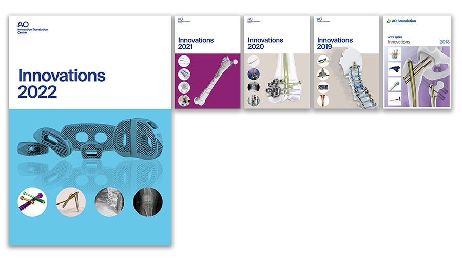
AO ITC Innovations Magazine
Find all issues of the AO ITC Innovations Magazine for download here.
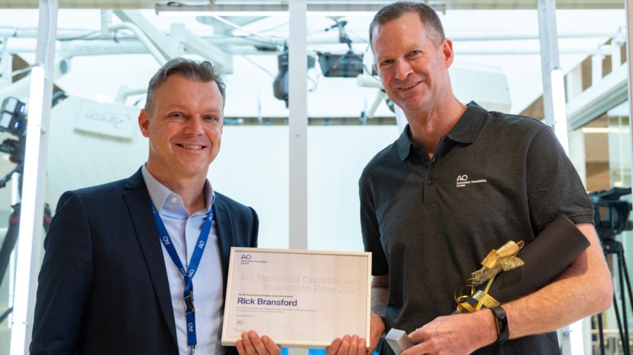
Innovation Awards
Recognizing outstanding achievements in development and fostering excellence in surgical innovation.