


Patient Specific Orthognathic Plates
Frank Wilde, Alexander Schramm
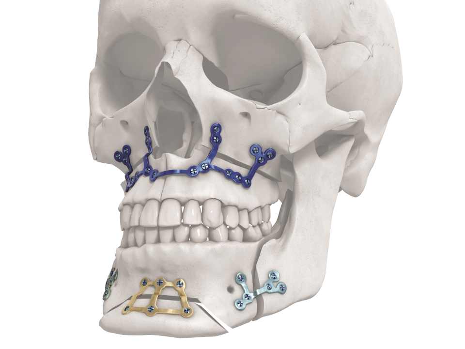 Fig 1 TruMatch Orthognathics Plates.
 Treatment planning for orthognathic surgery is complex and has traditionally been dependent on the surgeons personal clinical experience, 2-D x-rays and manual plaster model surgery. Such approaches lack detail about the 3-D configuration of relevant anatomical structures, meaning that planned movements cannot be accurately transformed into occlusal splints. Over the last decade, there has been considerable growth in the use of computer-assisted planning and surgery for the treatment of orthognathic deformities. However, computerized and customized wafers have not allowed surgeons to achieve desired accuracy of outcomes in maxillary repositioning. The recent development of TruMatch Orthognathics, a system of patient-specific 3-D printed osteotomy and drilling guides and personalized plates for orthognathic surgery, allows waferless maxillary positioning with a high level of accuracy. The TruMatch Orthognathics platform addresses the challenge of vertical maxillary positioning in cases of complex facial asymmetry, and supports accurate transfer of the surgical plan to the operating room. Additionally, the system reduces the need for splints and plate bending, and allows the surgeon to avoid critical anatomical features including vessels and nerves. The TruMatch Orthognathics platform integrates virtual surgical planning, and the production of intra-operative patient-specific tools and personalized implants. As well as enhancing accuracy, the system improves efficiency by optimizing pre-operative planning and reducing the number of procedural steps. Patient benefits include reduced operative time and pleasing aesthetic results.
Titanium 3-D Printed Plates
The titanium 3-D printed plates are individually designed to meet the requirements of patients and surgeons, and exist in different designs (Le Fort I, bilateral sagittal split osteotomy (BSSO) and genioplasty plates, Figs 2-4). The plates are intended to be used in conjunction with the titanium 3D-printed guides. The screw locations and vectors are defined according to surgical access, bone volume and the avoidance of key anatomical obstacles (nerves, tooth roots). Markers facilitate correct plate placement, and the plates are available with either 0.8 mm or 1.0 mm profile. The plates are compatible with MatrixOrthognathic and MatrixMidface screws and drill bits.
 Fig 2 Le Fort I titanium 3-D printed plates. A range of designs and patterns is available, including in-line or clover leaf hole patterns and 2+2 or 3+3 hole designs.
  Fig 3 BSSO titanium 3-D printed plates.
  Fig 4 Genioplasty 3-D printed titanium plates.
 Titanium 3-D Printed Surgical Guides
The surgical guides (Figs 5-8) are designed to assist with osteotomies and to accurately transfer the virtual surgical plan to the patient. The guides incorporate cutting slots to guide the planned osteotomies (according to the surgeons preference). Pilot hole locations and drilling vectors are defined according to surgical access, bone volume and the avoidance of key anatomical features. The guides include temporary fixation holes and are color-coded to the matching plates for ease of surgical use. Anatomical markers facilitate correct placement of the guides.
 Fig 5 TruMatch Orthognathics titanium 3-D printed surgical guides.
  Fig 6 BSSO drilling and cutting guide.
  Fig 7 Le Fort I drilling and cutting guide.
  Fig 8 Genioplasty drilling and cutting guide.
 Orthognathic Splints/Wafers
TruMatch Orthognathics splints are patient-specific devices used to transfer the virtual surgical plan to the operating room, indicating the steps of the surgery based on the occlusal information. Intermediate and final occlusion splints are available (Fig 9), with a range of impression depths and buccal contour widths. Use of the TruMatch Orthognathics titanium 3D-printed plates and guides reduces or completely obviates the requirement for splints.
 Fig 9 TruMatch Orthognathics splints, available for both intermediate (a) and final (b) stages of occlusion.
 Case Workflow
The surgeon uses PROPLAN CMF software to upload the patients (CB) CT data and to select the relevant options for planning, guides, splints, models and implants (Fig 10). The Proplan CMF software generates 2-D and 3-D visualizations of the pre-operative patient anatomy, which can be combined as appropriate with facial pictures and scans of the dentition. The technology allows virtual simulation and optimization of the skeletal osteotomies and reconstruction, and offers multiple cephalometric analysis options. Soft tissue simulation and photomapping in 2-D or 3-D is also possible. Following data upload, an interactive virtual surgical planning session is undertaken with a clinical engineer (Fig 10). The surgeon then approves the virtual surgical plan and the designs for the patient-specific tools and personalized implants. The guides, models and implants are then manufactured and delivered to the surgeon, who transfers the virtual plan to the patient in the operating room. The design workflow for plates and guides is shown in Fig 11.
 Fig 10 Case workflow.
  Fig 11 Design workflow.
 Clinical Case: 22-year-old male patient with Class III malocclusion
Case provided by Alexander Schramm and Frank Wilde, Germany
Patient profile and preoperative situation
A 22-year-old male patient was referred from a local orthodontist for evaluation of a combined orthodontic surgical approach for correction of a Class III malocclusion. The challenges included a frontal and lateral open bite in combination with a maxillary transversal deficiency (Fig 12 a-c). The patient showed a midfacial hypoplasia which resulted in concave facial profile and positive lip step. The large tongue showed lateral teeth impressions and the patient had an immature swallowing pattern. The young patient complained about his difficulty eating and especially biting. Prior to the start of the orthodontic treatment the third molars were removed. After an intensive case discussion with the orthodontist the first idea of a rapid palatal extension prior to the bimaxillary surgery was discarded and a two-piece Le Fort I osteotomy with maxillary advancement and posterior widening in combination with a mandibular setback was planned. The patient returned to the orthodontist to be set up for surgery.
 Fig 12 Pre-surgery lateral (a) and frontal views (b) and x-ray (c) showing Class III malocclusion, and frontal and lateral open bite.
 Treatment Plan
Following the additional orthodontic leveling and aligning, the surgical plan included the following procedures:
- Two-piece Le Fort I osteotomy with maxillary advancement
- Posterior maxillary widening to compensate the transversal deficiency
- Posterior maxillary impaction to close the open bite and normalize the occlusal plane
- Bilateral sagittal split osteotomy with mandibular setback and autorotation.
Virtual Surgical Planning
Preoperative multi-slice computer tomography (MSCT) was obtained and uploaded in Proplan CMF Connect. During a web-based meeting with a clinical engineer, the surgical procedures were planned (Fig 13). The skull was oriented in the natural head position in accordance to the Frankfurt horizontal plane and the bi-pupillary line, and a two-piece Le Fort I osteotomy with maxillary advancement and posterior impaction was planned. The plan included a posterior maxillary widening to compensate the transversal deficiency in relation to the mandible. A bilateral split osteotomy with mandibular setback and autorotation was simulated to achieve the final occlusion (Fig 13c-d). As the final step, the midline, the position of the incisors, the maxillary canting and the chin position were checked in relation to the facial midline, the lips and the natural head position. Fine tuning of the position was performed by moving the mono-block out of maxilla and mandible in final occlusion. A soft tissue simulation in the planned position of the bones was also performed (Fig 14).
 Fig 13 Preoperative situation (a-b); planned osteotomies (c-d) and final position (e-f).
  Fig 14 Pre-operative soft tissue situation (a-b) and soft tissue simulation in planned position (c-d).
 Implant and guide design
After the final position of the maxilla was virtually determined along with the necessary osteotomies, the placement, clustering and angulation of the screws was determined taking into consideration bone availability, teeth roots and surgical access. The plates were designed based on these constraints (Fig 15 a-d).
Next, the osteotomized bone segments (with the associated planned screw position and osteotomies) were virtually moved back to the preoperative position (Fig 16a-b). The guides were then designed with the drilling and cutting features as virtually planned (Fig 16c-d).
The plate and the guide were then produced from Pure Titanium Grade 2 using a laser melting process (Fig 17 a-b).
 Fig 15 Plate design (c-d) based on the planned position of the bone and screws (a-b).
  Fig 16 Guide design (c-d) based on the planned position of the osteotomies (a-b) and final screws.
  Fig 17 Plate (a) and guide (b) set ready for surgery.
 Intraoperative surgical details
Under general anesthesia via nasal endotracheal intubation, a maxillary vestibular approach was used to gain access for the two-piece Le Fort I osteotomy. Upon maxillary exposure, the surgical guide was placed and fixed with two MatrixMidface 1.5 mm screws on the maxilla (Fig 18a). The position of the guide was determined by the precise fit of the guide which allows a unique position. The screw holes were pre-drilled (black arrow) and Le Fort I osteotomy (white arrow) was performed in accordance to the surgical guide (Fig 18b). After removal of the guide the two-piece Le Fort I osteotomy was completed and the down fracture in combination with the midline split was performed (Fig 18c).
Maxillary positioning in all three dimensions (sagittal, transversal and vertical) was achieved by fixing the patient specific plate in accordance with the pre-drilled screw holes at the maxilla first and at the midface second (Fig 19a). Additional transversal stability of the two-piece Le Fort I osteotomy was achieved by using a transversal wire enforced palatal plate which was manufactured prior to surgery by the dental technician.
The new maxillary position in sagittal, transversal and vertical dimension is encoded in the shape of the patient specific plate. No additional splint (wafer) or intraoperative measurements were necessary for positioning of the maxilla. After closing the maxilla, a classical BSSO with semi rigid SplitFix fixation was performed (Fig 19b) and the final occlusion (Fig 19c) was adjusted using a splint (wafer) in final occlusion.
 Fig 18 Intraoperative guide positioning (a), maxillary osteotomy in accordance with the guide (b) and complete midline osteotomy (c).
  Fig 19 Intraoperative view of the plate attached in accordance with the primary pre-drilled screw holes (a); the BSSO fixed using a SplitFix plate (b); final outcome (c).
 Results and discussion
The patient did well postoperatively. A stable Class I occlusion could be achieved and the open bite could be closed safely (Fig 20 a-d). He had full sensation along the V2 and V3 distribution of the trigeminal nerve six weeks postoperatively. More recent postoperative images shown (Fig 21).
There are two main benefits of this waferless maxillary positioning. The first benefit is the high precision of maxillary positioning according to the virtual plan without the loss of vertical control of the maxilla. The authors could achieve an accuracy between plan and result of median below 0.5 mm in all 3 axes x, y and z (in a series of 12 cases). The second benefit is the significant reduction of surgery time of up to one hour due to the straight forward procedure, without the need of an intermediate splint/wafer, which eliminates the intraoperative plate bending and any measuring for the adjustment of the vertical dimension.
 Fig 20 Postoperative images (a-c) and x-ray (d) showing Class I occlusion and no open bite.
  Fig 21 a-c Postoperative appearance after removal of orthodontic brackets and wire,
 Patient Specific Procedures in CMF: State of the Art
New Frontiers in Orthognathic Surgery
Hazards and labeling
Due to varying countries’ legal and regulatory approval requirements, consult the appropriate local product labeling for approved intended use of the products described on this website. All devices on this website are approved by the AO Technical Commission. For logistical reasons, these devices may not be available in all countries worldwide at the date of publication.
Legal restrictions
This work was produced by AO Foundation, Switzerland. All rights reserved by AO Foundation. This publication, including all parts thereof, is legally protected by copyright.
Any use, exploitation or commercialization outside the narrow limits set forth by copyright legislation and the restrictions on use laid out below, without the publisher‘s consent, is illegal and liable to prosecution. This applies in particular to photostat reproduction, copying, scanning or duplication of any kind, translation, preparation of microfilms, electronic data processing, and storage such as making this publication available on Intranet or Internet.
Some of the products, names, instruments, treatments, logos, designs, etc referred to in this publication are also protected by patents, trademarks or by other intellectual property protection laws (eg, “AO” and the AO logo are subject to trademark applications/registrations) even though specific reference to this fact is not always made in the text. Therefore, the appearance of a name, instrument, etc without designation as proprietary is not to be construed as a representation by the publisher that it is in the public domain.
Restrictions on use: The rightful owner of an authorized copy of this work may use it for educational and research purposes only. Single images or illustrations may be copied for research or educational purposes only. The images or illustrations may not be altered in any way and need to carry the following statement of origin “Copyright by AO Foundation, Switzerland”.
Check www.aofoundation.org/disclaimer for more information.
If you have any comments or questions on the articles or the new devices, please do not hesitate to contact us.
“approved by AO Technical Commission” and “approved by AO”
The brands and labels “approved by AO Technical Commission” and “approved by AO”, particularly "AO" and the AO logo, are AO Foundation's intellectual property and subject to trademark applications and registrations, respectively. The use of these brands and labels is regulated by licensing agreements between AO Foundation and the producers of innovation products obliged to use such labels to declare the products as AO Technical Commission or AO Foundation approved solutions. Any unauthorized or inadequate use of these trademarks may be subject to legal action.
AO ITC Innovations Magazine
Find all issues of the AO ITC Innovations Magazine for download here.
Innovation Awards
Recognizing outstanding achievements in development and fostering excellence in surgical innovation.