


Trumatch CMF Solutions: Mandibular Reconstruction
Carl-Peter Cornelius, Gerson Mast, Goetz Giessler, Frank Wilde
Biplanar plug-on tandem cutting guide for raising and contouring bone flaps from the lateral scapular border and tip
Surgical techniques in craniofacial reconstruction using fibula and anterior iliac crest (DCIA) flaps are now well established. Such approaches using free flaps, computer-assisted planning and customized templates allow savings in operation time, improved accuracy of osteotomies and easy insetting. However, the use of flaps from the lateral scapular border and tip is less well defined in the literature.
The subscapular vascular system permits the retrieval of a wide array of different flaps in almost every conceivable combination of skin, fat, fascia, muscle and bone. Although the volume of vascularized bone from the lateral scapular border and inferior angle or tip is limited, the availability of extended soft tissue components at the same vascular pedicle offers valuable options in composite head and neck defects. In contrast to virtual surgical planning (VSP) and computer-assisted production of cutting templates for fibula and anterior iliac crest DCIA flaps similar planning methods and supporting tools to raise and contour the scapular border and tip were until recently considered impossible because of its anatomic features.
The cutting guide design for the scapular border is complicated by the fact that a muscle cuff (infraspinatus, teres minor/major and portions of subscapularis) must be preserved around the lateral border to maintain the blood supply provided by branches of the circumflex scapular artery.
This need for an intact muscle cuff precludes the unimpaired application of cutting guides, which in fibula or DCIA flaps can be conveniently placed on bare bony surfaces at the outer iliac wing or lateral aspect of the fibular shaft, respectively.
The fundamental need for uninterrupted muscular cover layers means that the lateral scapula must be accessed from two perpendicular planes (posterior and medial), a factor which has driven the development of a biplanar cutting guide design. Another feature in the specification catalogue is angulated slots or flanges to accurately define the resection of intermediate bone wedges and obtain
closing osteotomies. Reports of high rates of pseudoarthrosis between the scapular bone flap segments are the reason behind the demand to achieve maximum contact bony interfaces.
Biplanar plug-on tandem cutting guide design
Computer-assisted planning (ProPlan CMF/TRUMATCH CMF Solutions) provides a virtual 3 dimensional model for a detailed osseous reconstruction of the maxilla or mandible with sub-segments of the lateral scapular border and/or tip (Fig. 1) based on high-resolution CT scans of the craniofacial skeleton and scapular region. To transfer such graphical representation accurately into real surgery requires an assorted toolkit of stereolithography (STL) models, selective laser sintered (SLS) templates for bone contouring and sub-segmentation osteotomies and patient specific implants (PSI).
 Fig. 1a. Virtual planning (Synthes ProPlan CMF software). 3D superimposition of entire scapula providing a sub-segment of its lateral border to restore the anterior mandibular body on the left.
  Fig. 1b. Three bony sub-segments from the right lateral scapular border and tip filling the anterolateral mandibular defect.
 The specific anatomic conditions along the lateral scapular border led to the development of biplanar cutting guides consisting of a frame component and a vertical rod rider used in a plug on mode. (Fig. 2) The framework makes up a template which marks the outer margins of the in toto bone segment to be delivered in a first step (Fig. 2). It rests on two footplates at the cranial and caudal ends. Each of these footplates holds a connector socket to accommodate a removable vertical rod rider spanning the entire vertical length of the bone flap. The framework component is applied to the posterior bone surface after a rectangular channel has been opened through the infraspinatus muscle (Fig 2c). The bone flap segment is not cut out along its final borderlines initially. It remains affixed to the footplates until the wedge ostectomies have been performed, allowing its division into further sub-segments (Fig. 2c and 3). For this purpose, the rod rider component of the cutting guide equipped with two hovering pairs of slots and flanges is plugged on. It is convenient to continue the sub-segmentation on a side table, after ligation of the entire flap (Fig. 6, in Clinical Case section).
 Fig. 2a. Biplanar plug-on cutting guide for segmentation of the lateral scapular border and tip. Outer framework of SLS cutting guide (left) and vertical rod with slots and flanges (right).
  Fig. 2b. Vertical rod plugged on the footplates with slots and flanges located just above bone level when in situ.
  Fig. 2c. Outer SLS framework held to anatomic scapula specimen by screw fixation of the footplates. Initial cut out encompasses the footplates (green line). Final cut out subsequent to sub-segmentation proceeds inside caudal and cranial footplates (red lines).
 The transition zone between the lower lateral border and the tip of the scapula can be approached from the posterior aspect by means of the slots (Fig. 3a and b). Since the adjacent bone regions receive a separate blood supply either via the circumflex scapular artery or the angular branch exiting from the thoracodorsal artery, they can be divided into bipedicled sub-segments (Fig. 3a and b) following the transection of the muscle cuff (Fig. 6, in Clinical Case section). By contrast, the continuity of the muscular layers sandwiching the infraglenoid scapular bone portion must be preserved. Therefore, the only access to this region is via the medial aspect, which corresponds to the longitudinal bone edge of the in toto scapular segment. A gateway arch, hooked to the connecting bridge of the outer framework component, opens a pass-through for the pair of flanges put forward by the rod component at 90 to top over the bone edge.
The tandem ensemble of the bone flap mounted with both cutting guide components is turned onto its lateral side (Fig. 6b and c, in Clinical Case section). The muscle sheaths over the intended infraglenoid osteotomy location on either side are subperiosteally undermined. The wedge osteotomies within the muscle tunnel are then attained under the guidance of the flanges crossing the medial osteotomy line of the segment.
Finally the vertical rod component is lifted off the framework component and the sub-segmentation is completed with the transverse cuts along the inside of the upper and lower foot plates. The scapula sub-segment assembly is ready now to be folded (Fig. 3e) and for a double check inside the defect of the STL mandible model (Fig. 6d, in Clinical Case section).
 Fig. 3a. Mockup review of sub-segmentation procedure. Posterior plane - outline of wedge osteotomy. Pink acrylic resin = replica of in toto scapular bone segment.
  Fig. 3b. Posterior plane - outline of wedge osteotomy.
  Fig. 3c. Medial plane wedge osteotomy inside infraglenoid. Translucent silicon sleeve represents muscle tunnel (lateral periscapular infraspinatus, teres minor and major, subscapularis).
  Fig. 3d. Medial plane wedge osteotomy inside infraglenoid.
  Fig. 3e. Neomandibular sub-segments with closed gaps (replica) arranged to fit into mandibular defect, removed wedges.
 Conclusions
The biplanar cutting guide for the lateral scapular border and tip may be regarded as a further proof of concept that challenging anatomic conditions in free flap raising, contouring and insetting can be resolved by the application of innovative CAD/CAM techniques. It should however be noted that the soft tissue components on the subscapular vessel system are commonly not captured in computer-assisted planning at this time. Sound clinical judgement and decision making is still a prerequisite for proper planning and successful results at the current stage of technical evolution.
The use of virtual surgical planning in conjunction with STL models and the biplanar cutting guide offers many advantages in reconstructive mandibular and maxillary surgery, including negation of the guesswork inherent to freehand osseous contouring, unprecedented accuracy of wedge osteotomies, the optimization of bone healing by enabling maximum contact of the angulated bone ends and acceleration of the surgical procedure. The reduction of operating time and theatre costs largely compensates for the additional cost of VSP procedures, a factor which is particularly significant in fixed budget health care reimbursement.
One attractive surgical possibility is the immediate placement of dental implants allowing single stage reconstruction of the jaw and dentition. However, the bony cross section is not uniform across the length of the lateral scapular border and tip, and the shape is partially twisted. The varying bone stock is not ideal for primary implant insertion in an even distribution, and may require a subsequent local bone augmentation. The most recent recommendation therefore is that the insertion of dental implants should be postponed until the preconditions have been amended.
Clinical Case
A 58-year old male oncology patient required secondary mandibular reconstruction after composite resection of the floor of the mouth, mandibular symphysis, anterior body regions of the mandible and bilateral limited neck dissection. The existing reconstruction plate bridging the anterolateral mandibular defect was widely exposed through the intraoral mucosa. The chin and lower lip was sagging due to submandibular soft tissue shrinkage and lack of bone suspension. For secondary reconstruction, a two-in-one free flap from the subscapular vascular system containing the lateral scapular border and tip in combination with a latissimus dorsi flap was selected, since severe peripheral arterial occlusive disease prohibited the use of an osteofasciocutaneous fibula free flap. VSP was used to design the bony reconstruction with three sub-segments (total length 8.1 cm) from the right (nondominant arm) lateral scapular border and tip (Fig. 4).
 Fig. 4a. Anterior transview of right scapular bone, colour coded sub-segments projected along lateral border and tip; removed bone wedges reveal beveled intersegmental bone ends.
  Fig. 4b. Two-part cutting guide design - posterior view, outer framework (pale grey) and plug-on rod rider with slot and flange extensions (light green).
  Fig. 4c. Cutting guide design - view from medial margin ( longitudinal bone cut).
 Scapular SLS templates or cutting guides were manufactured for secondary resection of the mandibular bone stumps, along with a set of STL models and a patient specific mandibular reconstruction plate (PSMP) (Fig. 5).
 Fig. 5a. Stereolithographic (STL)-models. Selective laser sintering resection guides attached to both bodies of the STL mandible model delineating the anterior defect borders with their flanges. Resection guide rigged with targeting cylinder trocars to drill congruent burr holes for the PSMP.
  Fig. 5b. STL mandible model and assorted STL neomandibular scapular sub-segments.
  Fig. 5c. Milled patient-specific mandibular plate (PSMP) spanning the anterolateral defect of the STL mandibular model including the STL neomandible.
  Fig. 5d. Intraoperative size check with PSMP and STL neomandible.
 Intraoperatively, the circumflex scapular and thoracodorsal vascular pedicles were dissected to their common subscapular trunk and the angular branch supplying the scapular tip preserved (Fig. 6). In Fig. 6a, the angular vessel branch can be seen emerging from beneath the latissimus island to supply the scapular tip. An elliptical 18 cm x 7 cm myocutaneous latissimus dorsi flap was raised to provide coverage for the extensive submandibular soft tissue deficit. The in toto scapular bone flap was retrieved using the outer frame of the cutting guide (Fig. 6a). In tandem with the vertical rod and its extensions, the wedge osteotomies for segmentation were carried out on a side table (Fig. 6a and c). Prior to the flap transfer into the recipient site, the fit of the neomandibular segments was double checked within the defect of the STL model (Fig. 6d). Microanastomosis was performed end-to-end to the left maxillary artery and end-to-side to the internal jugular vein.
 Fig. 6a. Flap raising and bone contouring. Subscapular vascular network in situ - bifurcation into circumflex scapular, and thoracodorsal pedicles supplying lateral scapular border/tip and latissimus dorsi flaps (two-in-one). Outer frame of SLS cutting guide component secures to in toto bone flap.
  Fig. 6b. Posterior view of scapula bone flap and in tandem assembly of cutting guide components - on side table.
  Fig. 6c. Medial view highlighting the biplanar accessibility through the slot pair posteriorly and via the gateway and flanges medially.
  Fig. 6d. Scapular subsegments positioned into defect of the STL mandible model.
 Postoperative imaging confirmed minimal intersegmental gaps to the mandibular remnants with undisturbed healing but limited overall bone volume (Fig. 7a-c). Therefore removal of the PSPMP and a preimplantological augmentation with corticocancellous iliac bone grafts followed 16 months later.
 Fig. 7a. Postoperative imaging results. Panoramic X-ray 1 week postoperative.
  Fig. 7b. Axial CT scan 14 months postoperative confirms good matching and consolidation at the bony interfaces between native mandible and scapular sub-segments.
  Fig. 7c. 3D reformatted CT scan 14 months postoperative.
 Finally, dental implants were inserted (Fig. 8).
 Fig. 8a. Panoramic X-ray following insertion of enosseous dental implants.
  Fig. 8b. Attachment of implant-supported lower denture.
 Hazards and labeling
Due to varying countries’ legal and regulatory approval requirements, consult the appropriate local product labeling for approved intended use of the products described on this website. All devices on this website are approved by the AO Technical Commission. For logistical reasons, these devices may not be available in all countries worldwide at the date of publication.
Legal restrictions
This work was produced by AO Foundation, Switzerland. All rights reserved by AO Foundation. This publication, including all parts thereof, is legally protected by copyright.
Any use, exploitation or commercialization outside the narrow limits set forth by copyright legislation and the restrictions on use laid out below, without the publisher‘s consent, is illegal and liable to prosecution. This applies in particular to photostat reproduction, copying, scanning or duplication of any kind, translation, preparation of microfilms, electronic data processing, and storage such as making this publication available on Intranet or Internet.
Some of the products, names, instruments, treatments, logos, designs, etc referred to in this publication are also protected by patents, trademarks or by other intellectual property protection laws (eg, “AO” and the AO logo are subject to trademark applications/registrations) even though specific reference to this fact is not always made in the text. Therefore, the appearance of a name, instrument, etc without designation as proprietary is not to be construed as a representation by the publisher that it is in the public domain.
Restrictions on use: The rightful owner of an authorized copy of this work may use it for educational and research purposes only. Single images or illustrations may be copied for research or educational purposes only. The images or illustrations may not be altered in any way and need to carry the following statement of origin “Copyright by AO Foundation, Switzerland”.
Check www.aofoundation.org/disclaimer for more information.
If you have any comments or questions on the articles or the new devices, please do not hesitate to contact us.
“approved by AO Technical Commission” and “approved by AO”
The brands and labels “approved by AO Technical Commission” and “approved by AO”, particularly "AO" and the AO logo, are AO Foundation's intellectual property and subject to trademark applications and registrations, respectively. The use of these brands and labels is regulated by licensing agreements between AO Foundation and the producers of innovation products obliged to use such labels to declare the products as AO Technical Commission or AO Foundation approved solutions. Any unauthorized or inadequate use of these trademarks may be subject to legal action.
AO ITC Innovations Magazine
Find all issues of the AO ITC Innovations Magazine for download here.
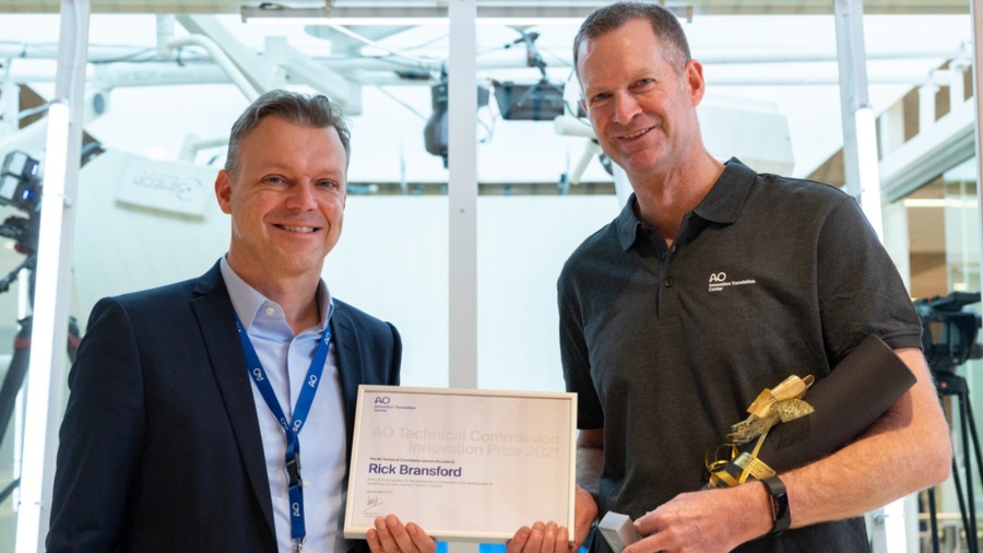
Innovation Awards
Recognizing outstanding achievements in development and fostering excellence in surgical innovation.