


TFN-ADVANCED Proximal Femoral Nailing System (TFNA)
Michael Blauth, Christopher Finkemeier, Hiroaki Minehara, Paulo Barbosa
 TFN-ADVANCED
 Although PFNA and TFN nailing systems have been successfully used in the past, several clinical issues for improvement have been identified by surgeons and engineers. Many of these issues have now been addressed and solved by implant and instrument design changes incorporated into the new TFNA nailing system.
The new nail system comprises short nails (lengths 170 mm, 200 mm, 235 mm) with distal nail diameters of 9, 10, 11 and 12 mm as well as long nails (lengths 260 to 480 mm in 20 mm increments) with distal nail diameters of 9, 10, 11, 12 and 14 mm. Such choice should address a broad range of patient anatomy. All nails are available in Caput-Collum-Diaphyseal (CCD) angles of 125°, 130° and 135°. The long nail provides three distal locking options including a unique oblique distal hole that has an offset angle of 10° to more appropriately target stronger bone in the condyles. Multi-planar locking also offers increased stability.
Features to avoid anterior cortical impingement
The complications of penetration or anterior cortical impingement while using long intramedullary nails for pertrochanteric femur fractures are due to a mismatch of the femoral antecurvation with the radius of curvature (ROC) of currently available cephalomedullary nails. Bazylewicz et al [1] reported that most of the intramedullary nails with a ROC of 1800 mm ended up in the anterior half of the space available for the nail with 16% within 3 mm of the anterior cortex. Patients that are shorter and/or have an increased femoral bow as measured on a lateral x-ray are more likely to have an anterior nail tip position or cortical impingement [2]. To thoroughly investigate this issue, a comprehensive 3D computer graphical anatomy study of the femur was conducted to serve as a basis for a new nail design [3]. Analyzing 27 Caucasian and 13 Japanese subjects, the ROC resulted in 962±157 mm (Caucasian subjects) and 790±151 mm (Japanese subjects). These results indicate significant differences between ethnicities and that the ROC should be closer to these values instead of 1500 mm, which is a frequently chosen radius in current nail systems on the market.
The new TFNA has a radius of curvature of 1000 mm to improve the anatomical fit and to help avoid impingement of the anterior cortex (Fig 1).
References
1) Bazylewicz DB, Egol KA, Koval KJ. Cortical encroachment after cephalomedullary nailing of the proximal femur: evaluation of a more anatomic radius of curvature. J Orthop Trauma. 2013 Jun; 27(6):303-307.
2) Roberts JW, Libet LA, Wolinsky PR. Who is in danger? Impingement and penetration of the anterior cortex of the distal femur during intramedullary nailing of proximal femur fractures: preoperatively measurable risk factors. J Trauma Acute Care Surg. 2012 Jul; 73(1):249-254.
3) Schmutz B, Kmiec S, Wullschleger M, et al. 3D computer graphical anatomy study of the femur: a basis for a new nail design. 2nd AOTrauma Asia Pacific Scientific Congress & TK Experts Symposium. May 2014; Seoul.
 Fig 1 The TFNA nail, illustrated in green, has a 1000 mm ROC and perfectly follows the antecurvation of most femurs. The blue nail demonstrates a less favorable fit of a simulated nail with 1500 mm ROC.
 Features to avoid loss of closed reduction during nail insertion
Surgeons often report some loss of reduction during nail insertion, specifically in cases involving nail insertion through a fractured greater trochanter. This often leads to an unintended varisation of the head-neck fragment (HNF) and a medialization of the HNF resulting in reduced bone contact in the calcar area (Fig 2 and 3).
The combination of a large proximal nail diameter and a very lateral entry point has been identified as a potential reason for such a loss of reduction. As a result, a smaller diameter nail with a laterally flattened profile to more appropriately respect the anatomy of the proximal lateral femoral wall would be advantageous. Both design features have been realized with the new nail. The smaller 15.66 mm proximal nail diameter of the TFNA (compared to 16.5 mm and 17 mm for PFNA/PFNA-II and TFN) and the LATERAL RELIEF CUT design (Fig 4) of the proximal nail end serve to reduce the potential impingement of the nail with the lateral femoral wall and the HNF. Both of these issues could result in varus malalignment and a loss of reduction, which remain key indicators for an increased risk of cut-out. The small proximal nail diameter also helps to preserve bone in the insertion area, which is especially beneficial in the femora of small stature patients.
Evaluating nail fatigue is a key stage in the preclinical analysis of new implant designs. The median fatigue limit for the TFNA nail was 24% higher than that of the Gamma 3 nail and 47% higher than that of the InterTAN nail. This increase in fatigue strength is likely attributed to the use of a high-strength Ti-Mo (Ti-15Mo) alloy and the design features of the nail (Fig 4c).
 Fig 2a-c A 60-year-old female patient with a 31-A2 fracture (a). Closed reduction on the traction table and insertion of the guide wire (b). With nail insertion, the HNF displaces to medial and varus (c).
  Fig 3a-d Closed reduction and nail insertion (a). With advancement of the PFNA, the HNF displaces to medial. This cannot be avoided by pushing the shaft from lateral with a ball spike pusher (b). The attempt to reduce the calcar with a collinear clamp results in pronounced varus malalignment (c and d).
  Fig 4a-c The LATERAL RELIEF CUT design of the nail (a) avoids impingement of the lateral cortex (b). The BUMP CUT design of the proximal hole for the head element (c) provides improved fatigue strength compared to existing nails of similar size.
 Features to avoid suboptimal placement of the head element
Apart from the newly introduced nail design features, which help to maintain a good reduction, it is also essential to place the head element in the correct position of the femoral head to avoid cut-out or cut-through. Numerous studies have demonstrated that a center/center position of the head element ensures the best clinical outcome. Multiple instrument features, including a multi hole drill sleeve for the facilitation of precise nail entry and aiming aids to accommodate the placement of the head element guide wire in the correct position have been added to the TFNA system to enable accurate implant placement. The insertion handle is radiolucent and has radiographic indicators to help the surgeon with exact guide wire placement for head element positioning in the lateral view (Fig 5). This feature, together with the guide wire aiming device, which checks guide wire position in the AP view, is influential in the placement of the guide wire in the center/center position of the femoral head. It also helps to reduce the number of imaging maneuvers and x-ray shots required.
 Fig 5 Illustration of the radiolucent aiming arm (a). Nail rotation has to be adjusted until the two radiographic lines on the insertion handle are parallel to both the femoral shaft and nail. This ensures that the guide wire is in the correct position in the lateral view (b, c). As a prerequisite for this, a true lateral projection of the proximal femur (ie, a 180° angle of the femoral neck and shaft) has to be established by rotating the C-arm from a neutral position to about 15° to compensate for the anteversion of the head and neck.
 Features to avoid cut-out and cut-through
Multiple biomechanical and finite element (FE) studies have illustrated that the purchase of implants in osteoporotic bone is compromised. A blade-shaped head element and augmentation have been proven to enhance implant stability and this is especially significant in a society with a growing ageing population and increasing cases of osteoporosis. Having a modular nailing system, which comprises a screw, blade, and augmentation, offers a distinct advantage when addressing specific fracture situations, local bone quality, and issues like suboptimal reduction and implant placement. The surgeon has the option to choose between the TFNA Helical Blade and the TFNA Screw for head element fixation (Fig 6), which accommodates differing surgical preferences and facilitates hospital standardization. It is recommended to use the helical blade in cases of poor bone quality because it allows for bone compaction around the head element and avoids the bone loss that occurs with the drilling and insertion of the standard hip screw. Optional holes in the blade or screw enable augmentation of the head element in cases where additional fixation is required (only in countries where augmentation is approved from a regulatory perspective). The benefit and efficacy of augmentation is of particular significance in an off-center position of the head element.
 Fig 6 The TFNA Helical Blade (a) and TFNA Screw (b) have an oblique lateral end that lies flush with the lateral cortex, therefore reducing head element protrusion into the soft tissues. Both the helical blade and screw are available in lengths of 70 to 130 mm with 5 mm increments.
 Features to avoid leg shortening and lateral protrusion of the head element
For reasons of versatility, the new TFNA system offers two locking options. The first option locks rotation of the head-neck element. The second option inhibits lateral sliding of the head-neck element, thus preventing shortening of the femoral neck and lateral protrusion of the head element (Fig 7).
 Fig 7 A built-in locking mechanism (a) facilitates rotational locking (b), which allows sliding of the screw or blade head element while blocking rotation. Static locking can be achieved by tightening the locking mechanism with a torque limiter to create a fixed construct with no head element movement. The static locking mode maintains the femoral neck length.
 Indications
The TFNA system is indicated for:
- Stable and unstable pertrochanteric fractures
- Intertrochanteric fractures
- Basal neck fractures
- Combination of pertrochanteric, intertrochanteric, and basal neck fractures
The long nails are additionally indicated for:
- Subtrochanteric fractures
- Pertrochanteric fractures with shaft fractures
- Pathologic fractures (including prophylactic use) in both trochanteric and diaphyseal regions
- Long subtrochanteric fractures
- Proximal or distal nonunions, malunions, and revisions
QUICK CLICK self-retaining technology
The QUICK CLICK self-retaining technology (Fig 1) is designed for easier and safer attachment of the nail to the insertion handle. An optional percutaneous set with larger instruments including protection sleeve and insertion handle are available for large stature patients. Another important feature of the instrumentation is its ability to enable interfragmentary compression when used in conjunction with a compression nut after rotation has been locked. Matching internal threads in implant and removal instruments facilitate implant removal.
 Fig 1 The self-retaining technology is used between the connecting screw and ball hexagonal screwdriver as well as between the insertion handle and nail to reduce the risk of accidental detachment and subsequent de-sterilization.
 Screw-only aiming arm
The TFNA offers surgeons the option to insert either a blade or a screw head element. The TFNA helical blade is designed to compress bone during insertion, which enhances implant anchorage and can reduce the risk of cut-out. As such it is regarded as particularly advantageous under osteoporotic bone conditions. However, there are still many surgeons that prefer to use the TFNA screw as the head element regardless of bone quality. Since these surgeons do not necessarily need the instrumentation that allows the insertion of either the blade or the screw, a screw-only aiming arm has been developed to further reduce instrument complexity and cost.
The screw-only aiming arm is offered for CCD angles of 125° and 130° (Fig 2). It has a coaxial locking mechanism that reduces the size of the aiming arm and decreases its foot-print in the instrument case (Fig 3). It presents the possibility of inserting the screw-only sleeve and locking it with just one hand. Interfragmentary compression is possible by means of a compression nut (Fig 4).
 Fig 2 The screw-only aiming arm can be attached to the insertion handle.
  Fig 3 The screw only guide sleeve is locked by a quarter turn of the locking mechanism.
  Fig 4 Once the TFNA screw has been locked in rotation, interfragmentary compression can be obtained by mounting a compression nut onto the TFNA screw inserter (a), advancing it until it abuts the guide sleeve (b), and then turning the buttress/compression nut clockwise.
 Hollow reamer
When the TFN-Advanced proximal femoral nailing system was launched in 2015, flexible and solid drill bits were offered to prepare the entry path of the nail. When fracture lines are located in the area of the intended nail insertion point, fracture fragments can be pushed apart when introducing these drill bits through the fracture lines causing a varus malreduction of the head-neck fragment. In order to avoid this clinical problem, an optional hollow reamer has been developed (Fig 5).
When using the hollow reamer, fracture fragments are not displaced because the instrument facilitates the removal of a cylindrical bone plug from the insertion area (Fig 6) without causing radial displacement forces to the surrounding bone.
 Fig 5 Opening options to prepare the nail entry path. All drill bits are also offered in longer versions for use with the percutaneous radiolucent insertion handle: (a) 16 mm drill bit, flexible, cannulated, for quick coupling for DHS/DCS; (b) 16 mm drill bit, cannulated, for quick coupling for DHS/DCS; (c) 16 mm hollow reamer, cannulated, for quick coupling for DHS/DCS.
  Fig 6 Cylindrical bone plug removed from the insertion area with the hollow reamer.
 Curved elevator and L-shaped elevator
Reduction in certain proximal femoral nailing cases still remains a clinical challenge. Surgeons from Japan especially emphasize the importance of anatomical reduction of the medial and anterior cortices to improve the stability of the fracture and the efficacy of the nail. With no bone support at the medial and anterior cortices there is a higher risk for shortening of the femoral neck and fixation failure.
Because of the need for dedicated reduction instruments to facilitate the required reduction maneuvers, two new instruments have been developed: the curved elevator (Fig 7) and the L-shaped elevator (Fig 8).
The curved elevator is intended to align shifted fragments in the proximal femur through a lateral or an anterior approach (Fig 9). The recommendation is to obtain an extramedullary type of reduction with good bone support.
The L-shaped elevator is radiolucent. This elevator is usually applied for the reduction of strong anteversion in the lateral view (Fig 10).
The elevators are currently only available in Japan. The provision of these instruments in other countries is under consideration.
 Fig 7 Curved elevator.
  Fig 8 L-shaped elevator
  Fig 9 Anterior approach (a) for use with the curved elevator. The lower pictures depict the fracture before (b), during (c), and after (d) reduction [1].
  Fig 10 Pushing down the anterior cortex of the proximal fragment can correct the anteversion. It is necessary to hold the elevator until blade or lag screw insertion.
 Case provided by Michael Blauth, Innsbruck, Austria
Case 1: Fall at home
An 83-year-old female patient sustained a 31-A.2.2 fracture of the right proximal femur after a fall at home (Figs 1-2). Intraoperative and postoperative images are shown (Figs 3-5).
 Fig 1 AP x-ray.
  Fig 2a-b Injury images.
  Fig 3a-c AP views of the closed reduction (a), measurement of the CCD angle, in this case 130° (b), and the final result with the blade in center/center position and the blade tip approximately one cm from the joint line (c). The distal end of the blade is flush with the lateral femoral cortex.
  Fig 4a-b Lateral views after closed reduction with a slight extension malalignment (a). The final result, with a slightly eccentric position of the blade (b).
  Fig 5a-b Postoperative images at day 3 after mobilization.
 Case provided by Michael Blauth, Innsbruck, Austria
Case 2: Pertrochanteric fracture
A 98-year-old female patient sustained a pertrochanteric fracture of the left proximal femur due to fall in her nursing home (Fig 1). There was significant pain and coxarthritis in the right hip, and hypertension. Surgery was performed within 24 hours. There was an indication for augmentation due to the instability of the fracture. The patient additionally suffered from osteoporosis and dementia.
 Fig 1a-c Injury images.
  Fig 2a-c Intraoperative images. Good reduction and implant placement. Peri-implant augmentation with PMMA V Plus cement to offer increased stability. Implants used: TFNA (170/10), 130 blade (85 mm), 4 ml of VERTECEM V+ cement.
  Fig 3a-b Postoperative x-rays.
  Fig 4a-b Follow-up x-rays after a few days. There was subsidence of the fracture with controlled sliding of the blade.
 Case provided by Hiroaki Minehara, Sagamihara, Japan
Case 3: Use of the hollow reamer in a clinical case
It is widely reported in the literature in Japan that there are many missed unstable femoral trochanteric fracture cases diagnosed only by x-ray, yet CT scans can clearly reveal the unstable fracture pattern.
A 77-year-old man suffered a right femoral trochanteric fracture (Figs 5-8). This case can be diagnosed as AO31-A1. However, the CT shows the detachment of the lesser trochanter (AO31-A2). Precise information of dangerous fracture patterns in advance might simplify the imaging of intraoperative reduction maneuvers and the use of the implants.
In this case, the fracture lines are located in the area of the intended nail insertion point. The 3-D reconstruction images distinctly show that the hollow reamer prevented the fracture fragments from being pushed apart when introducing the hollow reamer close to the fracture line.
 Fig 5 Preoperative images of the patient.
  Fig 6 Intraoperative picture of the use of the hollow reamer.
  Fig 7a-d Preoperative (a,c) and postoperative (b,d) 3-D CT images.
  Fig 8 Postoperative x-ray images.
 Innovations in femoral nailing (2014)
Innovations in femoral nailing (2015)
Reduction techniques in proximal femoral fractures (2016)
Hazards and labeling
Due to varying countries’ legal and regulatory approval requirements, consult the appropriate local product labeling for approved intended use of the products described on this website. All devices on this website are approved by the AO Technical Commission. For logistical reasons, these devices may not be available in all countries worldwide at the date of publication.
Legal restrictions
This work was produced by AO Foundation, Switzerland. All rights reserved by AO Foundation. This publication, including all parts thereof, is legally protected by copyright.
Any use, exploitation or commercialization outside the narrow limits set forth by copyright legislation and the restrictions on use laid out below, without the publisher‘s consent, is illegal and liable to prosecution. This applies in particular to photostat reproduction, copying, scanning or duplication of any kind, translation, preparation of microfilms, electronic data processing, and storage such as making this publication available on Intranet or Internet.
Some of the products, names, instruments, treatments, logos, designs, etc referred to in this publication are also protected by patents, trademarks or by other intellectual property protection laws (eg, “AO” and the AO logo are subject to trademark applications/registrations) even though specific reference to this fact is not always made in the text. Therefore, the appearance of a name, instrument, etc without designation as proprietary is not to be construed as a representation by the publisher that it is in the public domain.
Restrictions on use: The rightful owner of an authorized copy of this work may use it for educational and research purposes only. Single images or illustrations may be copied for research or educational purposes only. The images or illustrations may not be altered in any way and need to carry the following statement of origin “Copyright by AO Foundation, Switzerland”.
Check www.aofoundation.org/disclaimer for more information.
If you have any comments or questions on the articles or the new devices, please do not hesitate to contact us.
“approved by AO Technical Commission” and “approved by AO”
The brands and labels “approved by AO Technical Commission” and “approved by AO”, particularly "AO" and the AO logo, are AO Foundation's intellectual property and subject to trademark applications and registrations, respectively. The use of these brands and labels is regulated by licensing agreements between AO Foundation and the producers of innovation products obliged to use such labels to declare the products as AO Technical Commission or AO Foundation approved solutions. Any unauthorized or inadequate use of these trademarks may be subject to legal action.
AO ITC Innovations Magazine
Find all issues of the AO ITC Innovations Magazine for download here.
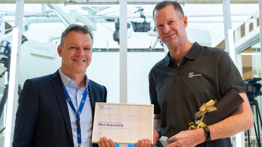
Innovation Awards
Recognizing outstanding achievements in development and fostering excellence in surgical innovation.