Matrix Orbit System
Matrix Orbital Set
The complex geometry of the bony orbit makes precise anatomical reconstruction somewhat challenging, particularly in cases of two wall fractures and when the deep orbital cone is affected. The new matrix orbital set was developed to address the need to have all necessary implants and instruments available for all types of fractures in this area.
Based on the matrix midface system, it is a dedicated set with implants and instruments specifically designed intended for orbital reconstruction. It includes a variety of existing implants, such as the orbital floor mesh plates in two versions (0.3 mm and 0.4 mm in thickness) as well as the curved 12-hole orbital plate, and the straight adaption plate with 20 holes. All implants match the sizes and hence the color coding of the matrix midface system being available in 0.5 mm (blue), 0.7 mm (pink) versions.
Furthermore, as orbital floor fractures are quite frequently associated with medial wall fractures, anatomical restoration, especially in the transition zone between both walls, is a demanding procedure. As described by Hammer [1], the orbital floor has an initial shallow convex section behind the rim, then inclines upward behind the globe, and inclines upward to meet the medial wall, creating a distinct bulge behind the globe. These convex curves of the medial wall and floor create a postbulbar constriction of the orbital cavity, which must be reconstructed when the orbit is rebuilt following fractures. Treatment is directed at precise anatomical reconstruction of orbital shape and volume in order to restore the correct position of the eye. To provide surgeons with an adequate implant that addresses the requirements of two wall acute orbital fractures or for secondary reconstruction of enophthalmos and dystopia, a new series of preformed orbital plates was developed for the new orbital matrix system.
Fig 1 Matrix orbital set.
Preformed Orbital Plates
The preformed orbital plates were developed based on the evaluation of more than 3,000 CT scans of patient data and then reduced to approximately 250 in order to find anatomical averages. In the end it was possible to reduce the number of plates down to two per side and still match the vast majority of all patients including males and females [2].
Unlike the existing 2-D mesh implants, the geometry of the new preformed plates will be adequate to match the individual anatomical situation of the patient in almost any case. However, the mesh parts can be individually adjusted if necessary. In these cases the solid part in the central posterior area needs to remain untouched. Areas of the orbit that do not require a bridging can be spared out by trimming the implant along the designated cutting lines in the height of the medial wall and/or length of the orbital floor area. The lateral anterior part of the plate is intentionally prebent higher than the orbital rim anatomy to allow free plate movement during plate positioning.
Fig 2a Preformed orbital plates.
The preformed orbital plates are indicated for trauma repair and reconstruction of fractures of the orbital floor, medial orbital wall, or combined fractures of floor and medial wall. It should be noted that in three-wall fractures where the lateral wall is also involved, a second orbital implant (ie, the mesh plate) must be used in addition to the preformed orbital plate.
Fig 2b Preformed orbital plates.
Fig 3 Implant placement according to the orbital landmarks: 1 Orbital rim, 2 Inferior orbital fissure, 3 Posterior orbital ledge, 4 Transition between the medial wall and orbital floor, 5 Optic canal, 6 Lacrimal fossa.
Bibliography
- Hammer B, Prein J (1995) Correction of post-traumatic orbital deformities: operative techniques and review of 26 patients. J Craniomaxillofac Surg; 23(2):8190.
- Metzger MC, Schn R, Tetzlaf R, et al (2007) Topographical CT-data analysis of the human orbital floor. Int J Oral Maxillofac Surg; 36:4553.
Orbital Retractor
The new orbital retractor was developed to address the need for better instrumentation to aid implant placement in cases of orbital fracture fixation. It is intended to minimize orbital soft-tissue prolapse and provide soft-tissue protection.
The retractor comes as a pair with one version for each side. Both are clearly marked as left and right and are also etched with a calibration scale on both sides that helps to estimate the anatomical situation in the patients orbit. The retractor is made out of stainless steel, yet it is malleable. Each version has a large and a small end with the design
following the orbital anatomy.
Along with the preformed orbital plates the retractor is part of the new matrix orbital set.
Fig 4ab Orbital retractors.
30-year-old male with fracture of left orbital floor and involvement of medial wall.
Case provided by Marc C Metzger, Freiburg, Germany
Fig 1 CT scan with fused image of virtual prebent orbital plate.
Hazards and labeling
Due to varying countries’ legal and regulatory approval requirements, consult the appropriate local product labeling for approved intended use of the products described on this website. All devices on this website are approved by the AO Technical Commission. For logistical reasons, these devices may not be available in all countries worldwide at the date of publication.
Legal restrictions
This work was produced by AO Foundation, Switzerland. All rights reserved by AO Foundation. This publication, including all parts thereof, is legally protected by copyright.
Any use, exploitation or commercialization outside the narrow limits set forth by copyright legislation and the restrictions on use laid out below, without the publisher‘s consent, is illegal and liable to prosecution. This applies in particular to photostat reproduction, copying, scanning or duplication of any kind, translation, preparation of microfilms, electronic data processing, and storage such as making this publication available on Intranet or Internet.
Some of the products, names, instruments, treatments, logos, designs, etc referred to in this publication are also protected by patents, trademarks or by other intellectual property protection laws (eg, “AO” and the AO logo are subject to trademark applications/registrations) even though specific reference to this fact is not always made in the text. Therefore, the appearance of a name, instrument, etc without designation as proprietary is not to be construed as a representation by the publisher that it is in the public domain.
Restrictions on use: The rightful owner of an authorized copy of this work may use it for educational and research purposes only. Single images or illustrations may be copied for research or educational purposes only. The images or illustrations may not be altered in any way and need to carry the following statement of origin “Copyright by AO Foundation, Switzerland”.
Check www.aofoundation.org/disclaimer for more information.
If you have any comments or questions on the articles or the new devices, please do not hesitate to contact us.
“approved by AO Technical Commission” and “approved by AO”
The brands and labels “approved by AO Technical Commission” and “approved by AO”, particularly "AO" and the AO logo, are AO Foundation's intellectual property and subject to trademark applications and registrations, respectively. The use of these brands and labels is regulated by licensing agreements between AO Foundation and the producers of innovation products obliged to use such labels to declare the products as AO Technical Commission or AO Foundation approved solutions. Any unauthorized or inadequate use of these trademarks may be subject to legal action.
AO ITC Innovations Magazine
Find all issues of the AO ITC Innovations Magazine for download here.
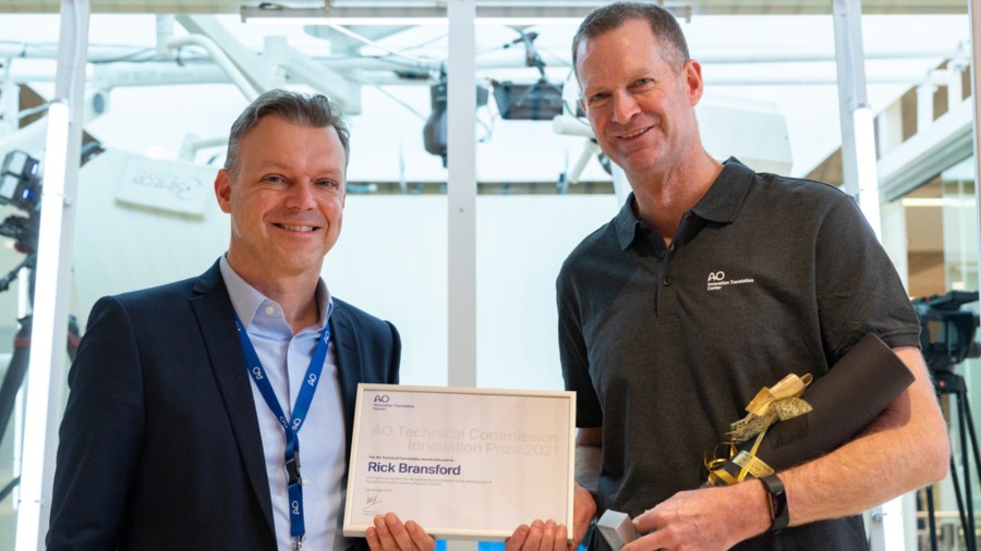
Innovation Awards
Recognizing outstanding achievements in development and fostering excellence in surgical innovation.


