


Patient Specific Plates for the Mandible
 Fig 1a: Patient specific plates for the mandible have the versatility to bridge almost all defect patterns in the mandible. Image shows continuity defect of the ramus angle body with the Hemimandibular Plate.
 Mandibular defects can be the consequence of segmental resection of the mandible due to malign/benign tumors, maxillofacial trauma caused by ballistic or avulsion injuries, multifragmentation, and end stage osteoradionecrosis (ORN). Reconstruction of the mandible is indicated for functional restoration, psychological recovery, and social reintegration of patients suffering from such defect conditions. In large wide-spanning defects covering more than the extent of a hemimandible, it is a first-line goal to rebuild the bone continuity along the base of the mandible. In smaller defects, a "functional" reconstruction of the former dentoalveoalar process is paramount to carrying dental implants in the future. Whenever possible, in determining the suitability and length of a bone or bone-containing flap, both the supporting mandibular infrastructure as well as a neoridge should be reconstructed to recreate an ideal intermaxillary relationship with a matching bed to achieve a dental implant-based functional prosthodontic rehabilitation and optimal facial esthetics. Patient specific plates can help to achieve this reconstruction (Fig 1a).
Virtual surgical planning using preoperative CT DICOM datasets of the defective CMF region, and the donor region from where the bone flap will be harvested, provides a detailed outline of the bony framework (eg, an autogenous neomandibular section consisting of an array of fibular segments).
The innovative milled patient specific mandible reconstruction plates represent a paradigm shift in mandibular reconstruction, since these individualized plates complete the virtual work flow in computer assisted surgery. The optimal assembly of the bony segments is no longer compromised by manually bent plates causing secondary dislocation, since there is no leeway space in between the bone surfaces of the segments and the inner side of the plate.
With patient specific plates for mandibular reconstruction, the design of the bone flap now becomes the prevalent parameter because the plate is fabricated to exactly fit to the bony surfaces. This eventually means that the bony framework dictates the reconstruction, which allows for more conformity with the original anatomy, augmenting accuracy. To transfer the surgical plan into surgery, cutting guides and repositioning templates, both for resecting and contouring the bone flap, are prefabricated with Selective Laser Sintering (SLS) from polyamide. Patient specific plates are conclusively brought into alignment with native mandible and the neomandibular segments by using drill guides integrated in the resection or cutting templates. By using the drill guides, the plate holes can be targeted exactly to the holes drilled into the bone without a temporary in situ application of the reconstruction plate.
The design of the bony segments and the overall framework is defined in an interactive planning session between the surgeon and a medical engineer. In oncologic surgery, a primary reconstruction is preceded by a virtual tumor resection for exact matching of the defect and the bony restoration. In secondary reconstruction, it will often be necessary to reposition collapsed bony remnants and to level their cut edges in order to define the real extent of the preexisting defect. Patient specific plates for the mandible have the versatility to bridge almost all defect patterns in the mandible (Fig 1abc). After exarticulation of a condyle, they are even compatible with the Matrix Mandible condylar head add-ons as a joint component for temporary replacement. The cutting guides, templates, and the patient specific mandibular reconstruction plates can be supplemented with stereolithographic (STL) models of the mandible, displaying the defect and the composed fibular segments as either a hybrid or as separate items. In the separate format, the models are an ideal instrument for double-checking. The defect size and the correct placement of the patient specific plates for the mandible are controlled by inserting the STL fibular segment assembly in situ. On a side table, the fitting of the real fibular segments into the defect of the STL model can be assessed.
Prior to planning, all clinical decisions are made by the surgeon in terms of resection lines, need for reduction of bony remnants, condylar processes, choice of bone or bone containing flap, dental rehabilitation, and plate profile to achieve adequate stability of the construct. One of the manifold options is to insert a stand-alone patient specific mandibular reconstruction plate, which is supplemented with matching bone grafts secondarily (eg, following postoperative radiotherapy).
 Fig 1b Anteroateral continuity defect: symphysis and body bilaterally Mandibular Arch Plate from angle to angle.
  Fig 1c Entire mandible defect apart from condylar processes Full Mandible Arch Plate.
 Case: Computer assisted mandibular reconstruction using fibula flap
A 58-year-old male patient had oral cancer (T4n0m0) infiltrating the alveolar process and the anterior border of the ascending ramus (Fig 2). The treatment plan involved resection, bilateral neck dissection (levels I to III), and primary mandibular reconstruction with a right osteomyofasciocutaneous fibula flap.
 Fig 2 Intraoral findings at patient's presentation: mixed ulcerous and leukoplakia-like tumor lesion (approximate size 3 cm x 6.5 cm) over the top of the right mandibular alveolar process extending from the premolar region back into the retromolar field. Biopsy: squamous cell carcinoma.
  Fig 3ad A 3-D CT reformatted image: tumor infiltration and destruction of the upper border cortices of the right mandible.
  Fig 4ad Virtual surgical planning: removal of tumor infiltrated bone by segmental resection with vertical osteotomies in mid ramus and in immediate postcanine region.
 At this stage, future dental implant insertion requires an alveolar process in a lingual shift position. To this end, the anterior segment is aligned with a medial offset. The posterior segment, which replaces the angle/anterior ramus region, is arranged with an overlapping zone. The inner cortex of the posterior segment in the area of intersection is trimmed to keep the restoration within the bounds of the original width of the angle. This results in a sort of "bayonet connection". The basal border of the mandibular body is not built up, since it is not functionally relevant.
 Fig 5ad Virtual mandibular reconstruction: rebuilding the mandible within the confines of the continuity defect using 2 fibular segments.
 With the design of the bony framework being ready, the reconstruction plate is molded to the geometry of the outer surface of the neomandibular division. The plate profile (thickness 2.0 or 2.5 mm) is chosen and the plate screw hole pattern is customized. Relative to the osteotomy sites, the fibular segment configuration, and the adjacent native bone, the number, position, and angulation (up to 15) of the plate screw holes is specified with respect to overall stability. A defined screw hole position facilitates accessibility for screw insertion and avoids interference with nerves, tooth roots, osteotomy interfaces, and existing/future implants.
Note: In contrast to a milled plate, a succinct set of abrupt bends or edges in a massive reconstruction plate is hardly bendable by hand. The screw length is preselected and screw convergence or tip collision (eg, in the symphyseal area) is precluded.
 Fig 6a-d Virtual application of the patient specific plate for mandibular reconstruction.
 To allow the soft tissue/vascular pedicled segments to shift into the "bayonet" assembly, a bone portion in between the segments has to be discarded. The inner cortex of the posterior segment needs appropriate trimming. The most distal cut along the fibula is placed about 5-6 cm above the ankle joint to preserve its stability.
 Fig 7ab Virtual 3-D reformatted bones of the right lower extremity. Lateral (a) and anterior (b) aspect with peroneal vessels, and transfer of the color-coded segments as used for the mandibular reconstruction.
 To target the screw holes for fixation of the milled patient specific mandible reconstruction plate, the guide is equipped with hollow cylinders for mounting of a trocar and predrilling. The cylinders have small openings at their base for cooling irrigation, when they are used after introducing the metal trocar drill guide. The templates are temporarily fixed to the fibula with monocortical 2.0 mm screws during the segmentation and drilling.
 Fig 8ab Design of fibular cutting guides with slots and flanges to angulate the ends of the segments. a Lateral view. b Posterior view.
 The flange for the posterior resection line conveys into a slot towards the inferior bony border. Just like the fibula cutting guides, the mandibular resection guides contain hollow cylinders for the mounting of the metal trocar drill guides, which exactly determine the patient specific plate screw hole position on the bony remnants. The transparent superimposition in Fig 9c reveals the interrelationship of the cylinders, the patient specific plate for mandibular reconstruction, and the underlying bony remnants.
Note: The images show the hollow cylindrical elements, the holes for irrigation/cooling, and the holes for screw fixation of the guides.
 Fig 9ad Resection guides for the mandible with vertical flanges.
  Fig 10ab SLS fabricated resection guides on the STL mandibular model with open defect.
  Fig 11 STL model of coupled fibular segments in "bayonet" assembly (left side being the posterior mandibular end obtained from foot end of fibula).
  Fig 12 STL model of "bayonet" fibular segments inside the SLS fibula cutting guide for the anterior segment (right side of photograph corresponds to the anterior mandibular end as well as the knee end of fibula).
  Fig 13 Patient specific plate for mandibular reconstruction with fibula graft. View from above. The plate was milled in a substractive mode according to the given specifications.
  Fig 14 Hemimandible patient specific plate applied to STL models of the mandible and coupled fibular segments.
 The bony surface of the mandible is covered with a tumor infiltrated soft envelope. The SLS resection guides are screw-fixated in place.
Prior to the resection with a reciprocating saw, the plate screw holes are predrilled using a metal drill guide, which is introduced into the cylinders of the SLS resection guides.
 Fig 15ab Guided tumor resection intraoperatively.
  Fig 15cd Guided tumor resection intraoperatively.
  Fig 16 Resulting continuity defect. The plate screw holes in the adjacent bony remnants can be recognized.
  Fig 17 Defect bridge with the patient specific plate for mandibular reconstruction, and filled with the STL model of the coupled fibular segments to control plate placement and defect extent/coverage. (a) Lateral view.(b) View from below.
 Fig 18 Osteomyofasciocutaneous fibula flap on a side table.
 Fig 18 a The bony rod is divided into 2 segments with the help of the SLS-cutting guide. The inner cortex of the posterior segment is removed for the "bayonet" style connection. b The osteomyofasciocutaneous fibula flap fitted into the defect of the STL mandibular model for double-checking.
  Fig 19 The osteomyofasciocutaneous fibula flap fitted into the real defect of the mandible, with screw fixation to the patient specific plate via the predrilled holes in the native mandible as well as the fibular neomandible.
  Fig 20 Completed reconstruction. The peorneal vessels are connected to superior thyroid artery and vein branches as recipient counterparts, while the skin island on top of the bone still waits for suturing.
  Fig 21 Skin island after suture fixation from intraoral view.
 To conclude, it can be noted that the substractive milling process for the manufacturing of patient specific plates for mandibular reconstruction eliminates the need for manual back and forth bending. This improves the fatigue strength and allows for a lower overall plate profile in comparison to standard reconstruction plates.
Patient specific plates for mandibular reconstruction present potential for time savings intraoperatively in exchange for time expenditure in the virtual planning and increased costs in production. Ideal plate fitting is dependent on preoperative planning accuracy, hence there is a need for time and thorough dedication at the initial planning stage.
A key advantage of patient specific plates for the mandible is the transfer of the bone work design into surgery without any compromise by insufficiently adapted plates that could lead to unwanted displacement, and in the extreme, to healing problems. A decisive requirement is to establish a complete digital workflow for the design and production of all necessary tools and models, to finally obtain an optimally fitting bony reconstruction stabilized by a patient specific plate.
Case provided by Carl Peter Cornelius, Munich, Germany.
 Fig 22ab Postoperative imaging: the 3-D reformatted CT scans and panoramic x-ray.
  Fig 22c-d Postoperative imaging: the 3-D reformatted CT scans and panoramic x-ray.
  Fig 22e Postoperative imaging: the 3-D reformatted CT scans and panoramic x-ray.
 Hazards and labeling
Due to varying countries’ legal and regulatory approval requirements, consult the appropriate local product labeling for approved intended use of the products described on this website. All devices on this website are approved by the AO Technical Commission. For logistical reasons, these devices may not be available in all countries worldwide at the date of publication.
Legal restrictions
This work was produced by AO Foundation, Switzerland. All rights reserved by AO Foundation. This publication, including all parts thereof, is legally protected by copyright.
Any use, exploitation or commercialization outside the narrow limits set forth by copyright legislation and the restrictions on use laid out below, without the publisher‘s consent, is illegal and liable to prosecution. This applies in particular to photostat reproduction, copying, scanning or duplication of any kind, translation, preparation of microfilms, electronic data processing, and storage such as making this publication available on Intranet or Internet.
Some of the products, names, instruments, treatments, logos, designs, etc referred to in this publication are also protected by patents, trademarks or by other intellectual property protection laws (eg, “AO” and the AO logo are subject to trademark applications/registrations) even though specific reference to this fact is not always made in the text. Therefore, the appearance of a name, instrument, etc without designation as proprietary is not to be construed as a representation by the publisher that it is in the public domain.
Restrictions on use: The rightful owner of an authorized copy of this work may use it for educational and research purposes only. Single images or illustrations may be copied for research or educational purposes only. The images or illustrations may not be altered in any way and need to carry the following statement of origin “Copyright by AO Foundation, Switzerland”.
Check www.aofoundation.org/disclaimer for more information.
If you have any comments or questions on the articles or the new devices, please do not hesitate to contact us.
“approved by AO Technical Commission” and “approved by AO”
The brands and labels “approved by AO Technical Commission” and “approved by AO”, particularly "AO" and the AO logo, are AO Foundation's intellectual property and subject to trademark applications and registrations, respectively. The use of these brands and labels is regulated by licensing agreements between AO Foundation and the producers of innovation products obliged to use such labels to declare the products as AO Technical Commission or AO Foundation approved solutions. Any unauthorized or inadequate use of these trademarks may be subject to legal action.
AO ITC Innovations Magazine
Find all issues of the AO ITC Innovations Magazine for download here.
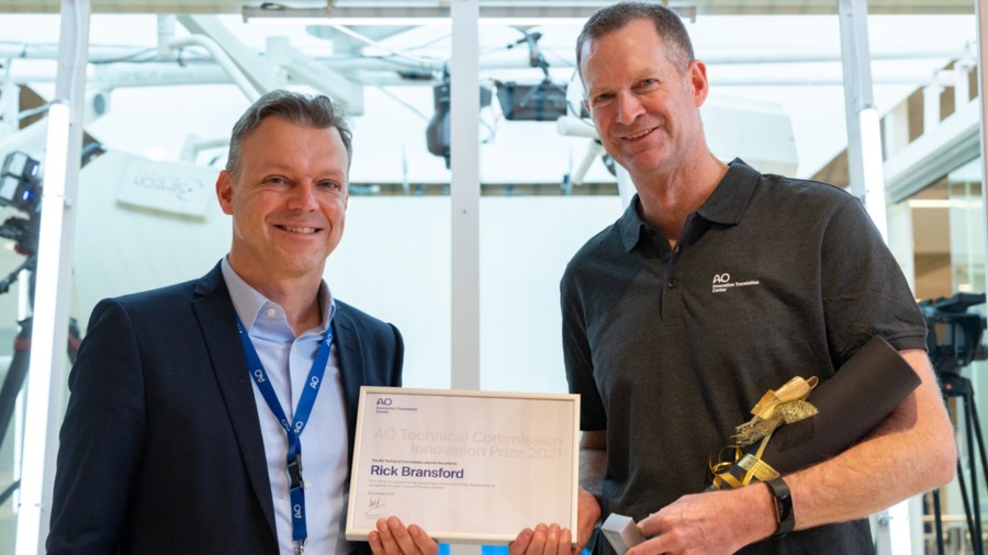
Innovation Awards
Recognizing outstanding achievements in development and fostering excellence in surgical innovation.