


Strut plate for fractures of the mandibular condylar process
 Fig 1: Strut Plate
 The Strut Plate comes in a left and right version and is commonly applied via an external approach. A transoral use is conditional on the rare prerequisite that the condyle bearing fragment is stable upon reduction.
The three subregions of condylar head, condylar neck, and base of the condylar process are identified using specific landmarks and reference lines (Fig 2):
The posterior ramus line (base line) running along the posterior border of the ascending ramus.
The sigmoid notch line running through the deepest point of the sigmoid notch and perpendicular to the posterior ramus line.
The condylar head reference line running perpendicular to the posterior ramus line below the lateral pole of the condylar head. The height of the lateral pole is determined by the diameter of a circle (2-D) or a sphere (3-D), whose arc best fits with the upper lateral boundaries of the lateral pole.
Nonetheless, during the last decade, open reduction and internal fixation techniques have been increasingly applied in treatment concepts accompanied by the development of standardized surgical approaches, instrumentation and osteosynthesis hardware. To circumvent the facial nerve and its branches, an endoscopically-assisted transoral approach has been advocated. From a biomechanical standpoint, a two mini-plate fixation for fractures of the base of the condylar process or the condylar neck was considered necessary to secure enough stability, and regarded most handy in application via the external or transoral route.
 Fig 2: Subregions of the condylar process
 The Lambda Plate (Fig 3a) is particularly suitable for fractures within the narrow-neck zone of the condylar process with its limited lateral bone surface. The linear upper fixation arm can be placed far cranially to extend over fracture lines even in the high neck. Though the plate may be applied within a wide vertical range down to the height of the mandibular foramen, it should not be overlapped by the anterior arm. The Lambda Plate comes in a left and right version. The converging midportion of the plate provides the required stability. The preferred surgical approach is external.
The Trapezoidal Plate (Fig 3b) is designed in a grid shape with two parallel rods at the top and the base connecting two larger merging bars at the sides. The distance between the holes at the top determines the uppermost placement position of the plate. Usually this will correspond to the width of the lower neck. The trapezoidal plate is conically molded to match with the curved lateral surface of the transitional zone between the base of the condylar process and the neck. The plate is applicable in a large diagonal field spanning downwards below the level of the sigmoid notch. The plate allows for external or transoral surgical approaches.
 Fig 3ab: Lambda (left) and Trapezoidal (right) plates
 Case: Mandible Fracture
Case provided by Carl-Peter Cornelius, Munich, Germany
An 84-year-old female patient with a triple fracture in the edentulous atrophic mandible (Luhr Class II): displaced condylar based fractures bilaterally in combination with a fracture in the anterior body on the right. Prosthetic restoration with full dentures.
Fig 1 Preoperative 3-D CT scans:
a) Frontal view. Right anterior body fracture associated with slight widening of the mandibular arch.
b) Dorsal view. Shortening of both rami due to lateral override displacement and medial angulation of both condylar bearing fragments, partial medial dislocation out of the fossa of the right condylar head.
c) Right lateral view. Lateral override of posteriorly displaced condyle bearing fragment and decreased ramus height.
d) Left lateral view. Lateral override position and posteromedial angulation of condyle bearing fragment.
 Fig 1 Preoperative 3-D CT scans
 Fig 2:
e) Intraoperative situation. Reduced condyle bearing fragments fixed with strut plates via retromandibular transparotid approaches.
f) Intraoperative situation, showing the mandible after fracture reduction and right paramedian plate osteosynthesis.
g) Intraoperative situation. Reduced condyle bearing fragments fixed with strut plates via retromandibular transparotid approaches.
h) Intraoperative situation. Reestablished occlusion, with full dentures in place.
 Fig 2
Fig 2 Fig 3: Postoperative panoramic x-ray
 Fig 3
Fig 3 Hazards and labeling
Due to varying countries’ legal and regulatory approval requirements, consult the appropriate local product labeling for approved intended use of the products described on this website. All devices on this website are approved by the AO Technical Commission. For logistical reasons, these devices may not be available in all countries worldwide at the date of publication.
Legal restrictions
This work was produced by AO Foundation, Switzerland. All rights reserved by AO Foundation. This publication, including all parts thereof, is legally protected by copyright.
Any use, exploitation or commercialization outside the narrow limits set forth by copyright legislation and the restrictions on use laid out below, without the publisher‘s consent, is illegal and liable to prosecution. This applies in particular to photostat reproduction, copying, scanning or duplication of any kind, translation, preparation of microfilms, electronic data processing, and storage such as making this publication available on Intranet or Internet.
Some of the products, names, instruments, treatments, logos, designs, etc referred to in this publication are also protected by patents, trademarks or by other intellectual property protection laws (eg, “AO” and the AO logo are subject to trademark applications/registrations) even though specific reference to this fact is not always made in the text. Therefore, the appearance of a name, instrument, etc without designation as proprietary is not to be construed as a representation by the publisher that it is in the public domain.
Restrictions on use: The rightful owner of an authorized copy of this work may use it for educational and research purposes only. Single images or illustrations may be copied for research or educational purposes only. The images or illustrations may not be altered in any way and need to carry the following statement of origin “Copyright by AO Foundation, Switzerland”.
Check www.aofoundation.org/disclaimer for more information.
If you have any comments or questions on the articles or the new devices, please do not hesitate to contact us.
“approved by AO Technical Commission” and “approved by AO”
The brands and labels “approved by AO Technical Commission” and “approved by AO”, particularly "AO" and the AO logo, are AO Foundation's intellectual property and subject to trademark applications and registrations, respectively. The use of these brands and labels is regulated by licensing agreements between AO Foundation and the producers of innovation products obliged to use such labels to declare the products as AO Technical Commission or AO Foundation approved solutions. Any unauthorized or inadequate use of these trademarks may be subject to legal action.
AO ITC Innovations Magazine
Find all issues of the AO ITC Innovations Magazine for download here.
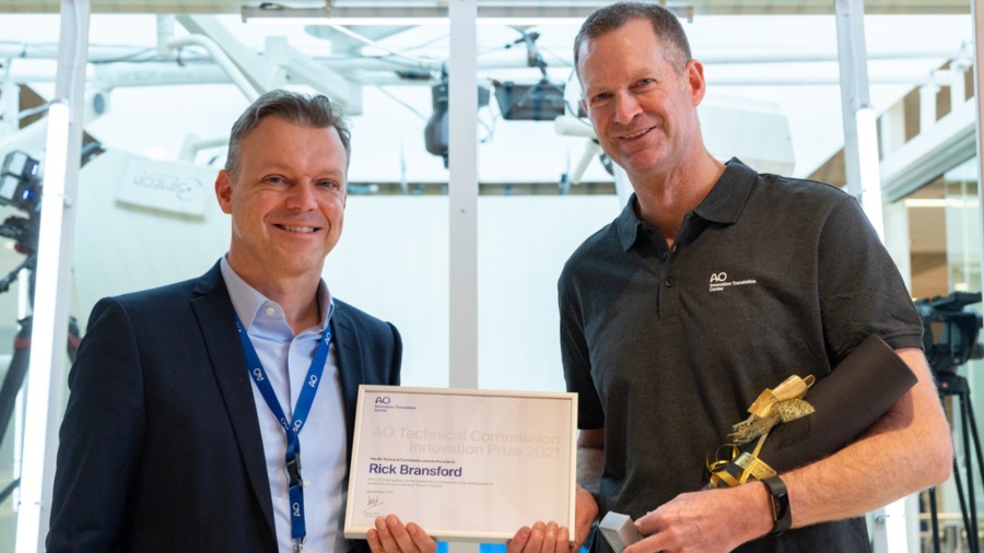
Innovation Awards
Recognizing outstanding achievements in development and fostering excellence in surgical innovation.